QL5/QL1
30
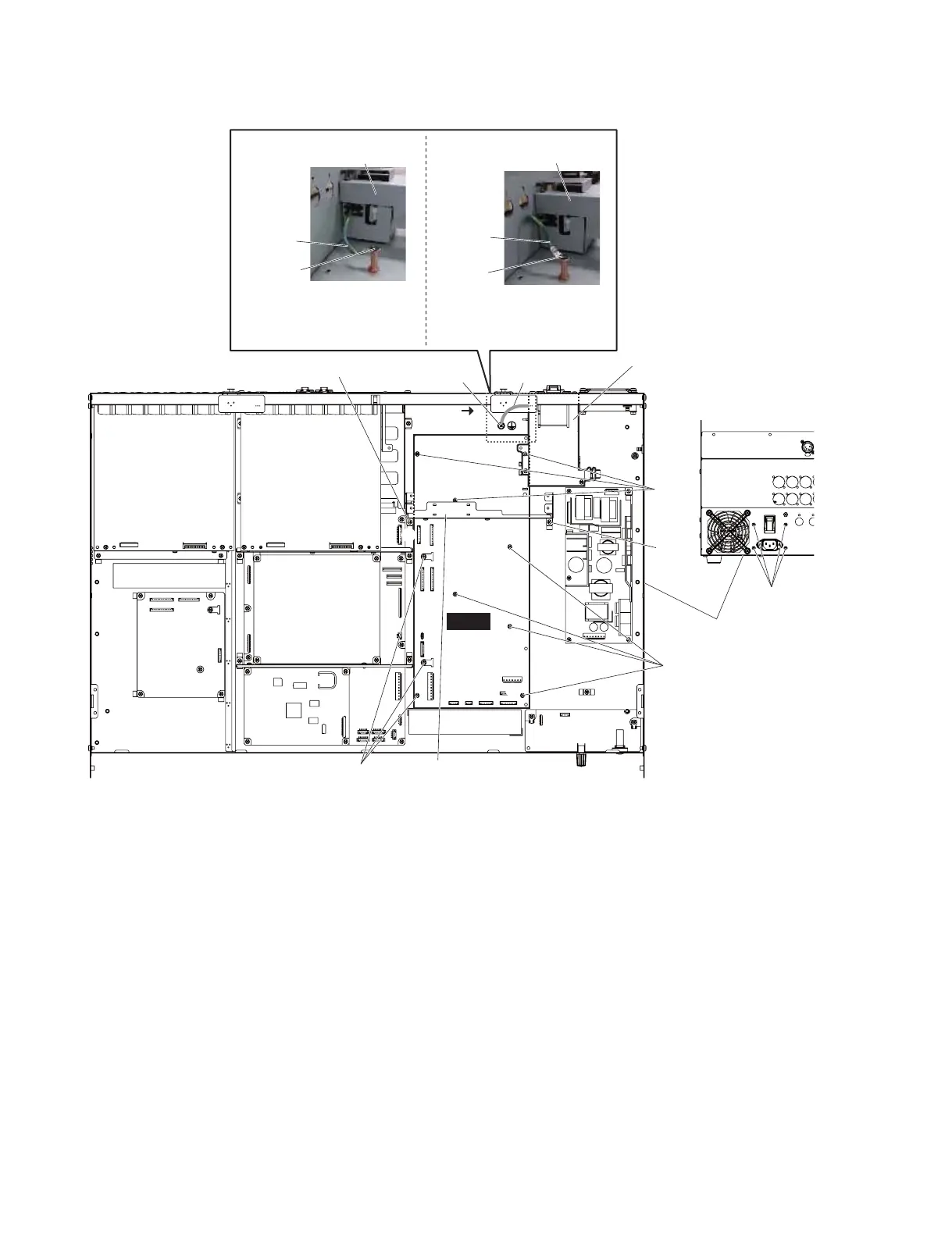
A-13. DCM Circuit Board
(Time required: About 17 minutes)
A-13-1
Remove the side pad assembly L and R. (See Procedure 1)
A-13-2 Fix the control panel L assembly. (See procedure 2)
A-13-3 Remove the DA (1/2, 2/2) circuit board.
(See procedure A-10)
A-13-4 Remove the JK circuit board assembly.
(See procedure A-11)
A-13-5 Remove the AC L assembly. (See procedure A-12)
A-13-6 Remove the two (2) screws marked [440]. The DA
angle L can then be removed. (Fig. 8)
* When installing the DA angle L, tighten the screws
q
,
w
shown in fig. 8 in numerical order.
A-13-7 Remove the ten (10) screws marked [200]. The DCM
circuit board can then be removed. (Fig. 8)
* When installing the DCM circuit board, tighten the
screws
A
to
B
shown in fig. 8 in numerical order
and then tighten the other screws.
Fig. 8
(図8)
A-13. DCM シート
(所要時間:約 17 分)
A-13-1 サイドパッド Ass'yL,R を外します。(1 項参照)
A-13-2 コンパネ LAss'y を固定します。(2 項参照)
A-13-3 DA(1/2、2/2)シートを外します。(A-8 項参照)
A-13-4 JK シート Ass'y を外します。(A-11 項参照)
A-13-5 ACLAss'y を外します。(A-12 項参照)
A-13-6 [440] のネジ 2 本を外して、DA アングル L を外
します。(図 8)
※ DA アングル L を取り付ける際は、図 8に示す q、w
の順にネジを締めてください。
A-13-7 [200] のネジ 10 本を外して、DCM シートを外し
ます。(図 8)
※ DCM シートを取り付ける際は、図 8に示す
A
→
B
の順にネジを締めてから他のネジを締めてください。
r"WJFX
(A 視野)
Ground wire
(アース線)
Ground wire
(アース線)
Ground wire
(アース線)
0,
/(
Fix the earth line facing downwards.
(アース線を下向きに固定。)
When the earth line is fixed facing
upwards, it will contact the JK sheet.
(アース線を上向きに固定すると
JK シートと接触します。)
[300]
[310]
DCM
[440]
[440]
[310]
[310]
AC L ASSEMBLY
(ACLAss'y)
AC L ASSEMBLY
(ACLAss'y)
AC L ASSEMBLY
(ACLAss'y)
DA ANGLE L
(DA アングル L)
q
A
B
w
3FBSWJFX(裏面)>
5PQWJFX(上面)>
"
BOTTOM L ASSEMBLY
(ボトムLAssy)
[200]
[200]
[200]

 Loading...


