QL5/QL1
31
A-14. ACSW Circuit Board, AC Inlet Assembly,
PSW Connector Assembly
A-14-1
Remove the side pad assembly L and R. (See Procedure 1)
A-14-2 Fix the control panel L assembly. (See procedure 2)
A-14-3 Remove the DA (1/2, 2/2) circuit board.
(See procedure A-8)
A-14-4 Remove the JK circuit board assembly.
(See procedure A-11)
A-14-5 Remove the AC L assembly. (See procedure A-12)
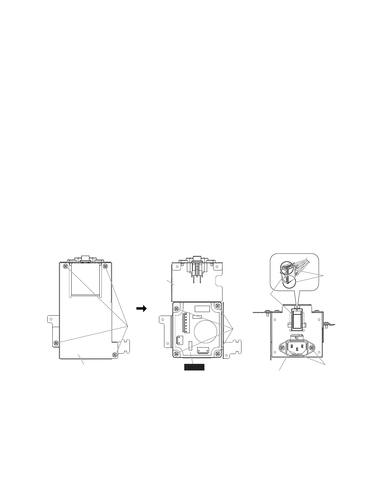
A-14-6 Remove the four (4) screws marked [130]. The AC
shield top can then be removed. (Fig. 9)
A-14-7 ACSW Circuit Board
(Time required: About 17 minutes):
A-14-7-1
Remove the four (4) screws marked [90]. The ACSW
circuit board can then be removed. (Fig. 9)
A-14-8 AC Inlet Assembly
(Time required: About 16 minutes):
A-14-8-1
Remove the two (2) screws marked [40]. The AC inlet
assembly can then be removed. (Fig. 9)
A-14-9 PSW Connector Assembly
(Time required: About 16 minutes):
A-14-9-1
Hold down the claws of the PSW connector assembly
from inside, and remove the PSW connector assembly
from the outside of the AC shield bottom. (Fig. 9)
Fig. 9
(図9)
<Rear view(裏面)>
<Top view(上面)>
AC SHIELD TOP
(AC シールドトップ)
[130]
AC SHIELD BOTTOM
(AC シールドボトム)
AC INLET ASSEMBLY
(インレット Ass'y)
PSW CONNECTOR
ASSEMBLY
(PSW 束線)
[90]
[40]
ACSW
Claw
(ツメ)
A-14. ACSW シート、インレット Ass'y、PSW
束線
A-14-1 サイドパッド Ass'yL,R を外します。(1 項参照)
A-14-2 コンパネ LAss'y を固定します。(2 項参照)
A-14-3 DA(1/2、2/2)シートを外します。(A-8 項参照)
A-14-4 JK シート Ass'y を外します。(A-11 項参照)
A-14-5 ACLAss'y を外します。(A-12 項参照)
A-14-6 [130] のネジ 4 本を外して、AC シールドトップ
を外します。(図 9)
A-14-7 ACSW シート
(所要時間:約 17 分)
:
A-14-7-1
[90] のネジ 4 本を外して、ACSW シートを外し
ます。(図 9)
A-14-8 インレット Ass'y
(所要時間:約 16 分)
:
A-14-8-1
[40] のネジ 2 本を外して、インレット Ass'y を外
します。(図 9)
A-14-9 PSW 束線
(所要時間:約 16 分)
:
A-14-9-1
PSW 束線のツメを押さえながら、PSW 束線を
AC シールドボトムの外側から引き抜きます。
(図9)
 Loading...


