QL5/QL1
32
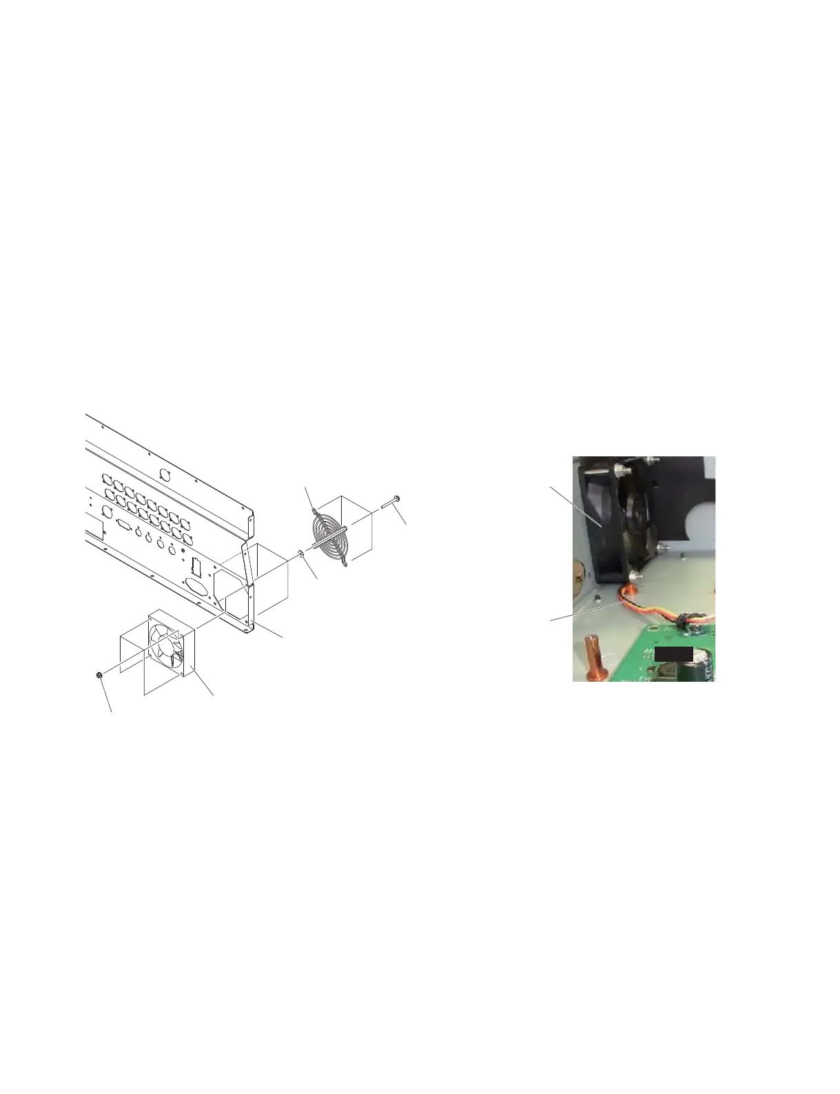
Fig. 10
(図10)
A-15. DC Fan Motor
(Time required: About 16 minutes)
A-15-1
Remove the side pad assembly L and R. (See Procedure 1)
A-15-2 Fix the control panel L assembly. (See procedure 2)
A-15-3 Remove the DA (1/2, 2/2) circuit board.
(See procedure A-8)
A-15-4 Remove the JK circuit board assembly.
(See procedure A-11)
A-15-5 Remove the AC L assembly. (See procedure A-12)
A-15-6 Remove the four (4) screws marked [20e], the four (4)
plain washers marked [20f] and the four (4) hexagonal
flange nuts marked [20g]. The finger guard and DC
fan motor the can then be removed. (Fig. 10)
* When installing the DC fan motor, take note of the
insertion of the fan connector assembly. (Fig. 10)
A-15. DC ファンモーター
(所要時間:約 16 分)
A-15-1 サイドパッド Ass'yL,R を外します。(1 項参照)
A-15-2 コンパネ LAss'y を固定します。(2 項参照)
A-15-3 DA(1/2、2/2)シートを外します。(A-8 項参照)
A-15-4 JK シート Ass'y を外します。(A-11 項参照)
A-15-5 ACLAss'y を外します。(A-12 項参照)
A-15-6 [20e] のネジ 4 本と [20f] の平座金みがき丸 4 枚と
[20g] のナット6角フランジ 4 個を外して、フィ
ンガーガードと DC ファンモーターを外します。
(図 10)
※ DC ファンモーターを取り付ける際は、ファン束線の
挟み込みに注意してください。(図 10)
[20e]
[20f]
[20g]
FINGER GUARD
(フィンガーガード)
DC FAN MOTOR
(DC ファンモーター)
DC FAN MOTOR
(DC ファンモーター)
FAN CONNECTOR ASSEMBLY
(ファン束線)
REAR L ASSEMBLY
(リア LAssy)
DCM
 Loading...


