QL5/QL1
35
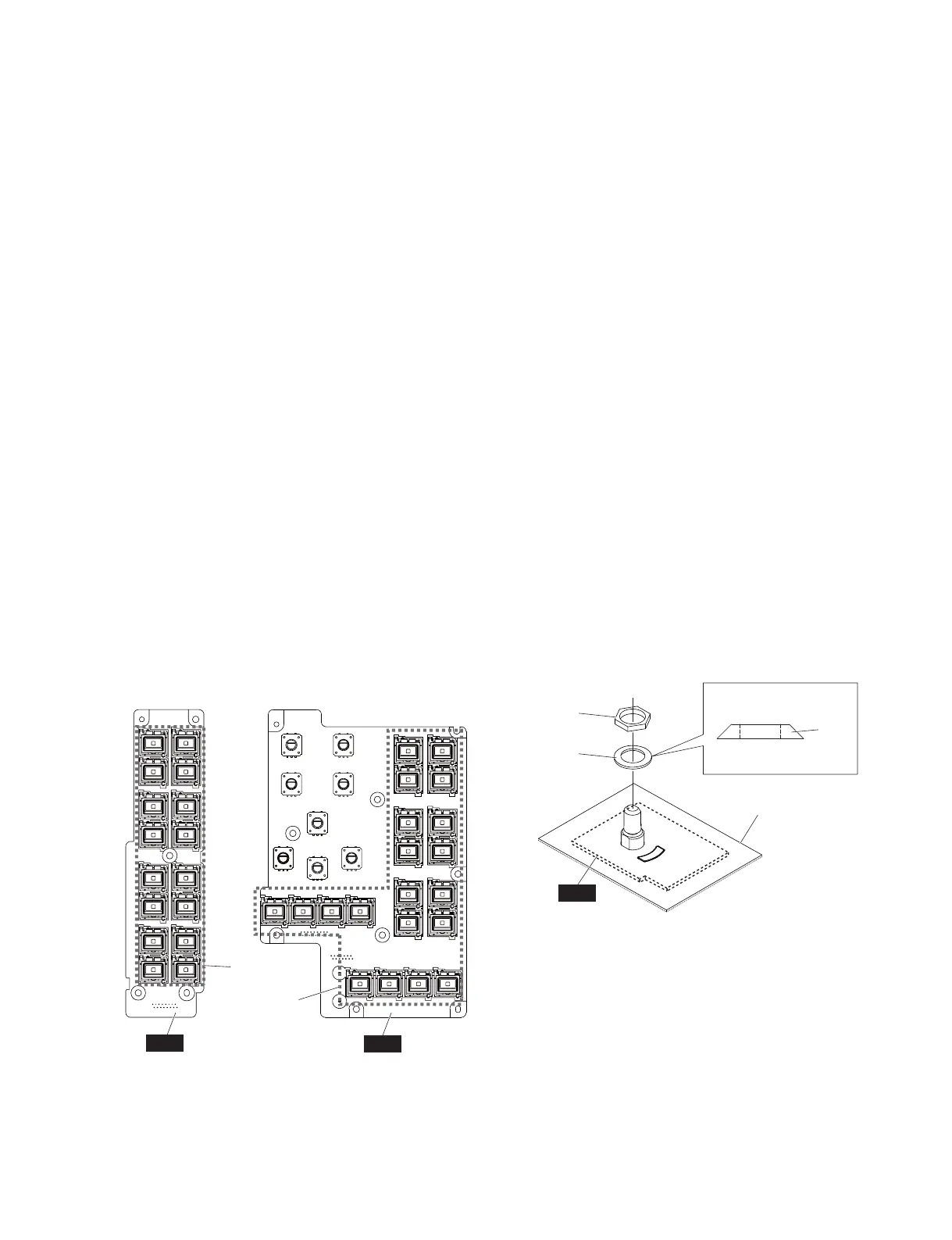
Fig. 13
(図13)
Fig. 14
(図14)
B-4. PNR シート
(所要時間:約 10 分)
B-4-1 サイドパッド Ass'yL,R を外します。(1 項参照)
B-4-2 コンパネ LAss'y を外します。(2 項参照)
B-4-3 コントロールパネル面より、[430] のエンコーダー
ノブ 1 個、[440] のエンコーダーノブ 2 個、[450]
のエンコーダーノブ 1 個、[460] のエンコーダー
ノブ 1 個、[470] のエンコーダーノブ 3 個を外し
ます。(図 12)
B-4-4 [230] のネジ 9 本を外して、PNR シートを外しま
す。(図 12)
※ PNR シートには、下記のボタンがついています。
(図 13)
・[30a]:ボタン(小)四角 20 個
B-5. ENC シート
(所要時間:約 7 分)
B-5-1 サイドパッド Ass'yL,R を外します。(1 項参照)
B-5-2 コンパネ LAss'y を外します。(2 項参照)
B-5-3 コントロールパネル面より、[480] のT−Tノブ
1 個を外します。(図 12)
B-5-4 [371] の皿バネ座金 1 個と [372] の管用ナット 1
個を外して、ENC シートを外します。(図 14)
※ ENC シートを取り付ける際は、図 14 を参照して [371]
の皿バネ座金の向きに注意してください。
B-4. PNR Circuit Board
(Time required: About 10 minutes)
B-4-1
Remove the side pad assembly L and R. (See Procedure 1)
B-4-2
Remove the control panel L assembly. (See procedure 2)
B-4-3 Remove the encorder knob marked [430], the two
(2) encorder knobs marked [440], the encorder knob
marked [450], the encorder knob marked [460] and
the three (3) encorder knobs marked [470] from the
control panel side. (Fig. 12)
B-4-4 Remove the nine (9) screws marked [230]. The PNR
circuit board can then be removed. (Fig. 12)
* The PNR circuit board contains the following
buttons. (Fig. 13)
· [30a]: Button S (Small) Square 20 pcs.
B-5. ENC Circuit Board
(Time required: About 7 minutes)
B-5-1
Remove the side pad assembly L and R. (See Procedure 1)
B-5-2
Remove the control panel L assembly. (See procedure 2)
B-5-3 Remove the T-T knob marked [480] from the control
panel side. (Fig. 12)
B-5-4 Remove the spring washe marked [371] and the nut
marked [372]. The ENC circuit board can then be
removed. (Fig. 14)
* When installing the ENC circuit board, refer to Fig.14
and take note of the direction of the spring washer
marked [371].
PNL
PNR
[20a] x 16
[30a] x 20
<Top view(上面)>
[371]
[371]
[372]
CONTROL PANEL L ASSEMBLY
(コンパネ LAss'y)
ENC
Top side(上側)
Bottom side(底側)
↑
↓

 Loading...


