QL5/QL1
51
<Top view(上面)> <Top view(上面)><Bottom view(底面)>
AC SHIELD TOP
(AC シールドトップ)
[130]
[150]
AC SHIELD PLATE
(AC シールド板)
AC SHIELD BOTTOM
(AC シールドボトム)
AC SHIELD BOTTOM
(AC シールドボトム)
[150]
[90]
ACSW
<Rear view(裏面)>
AC INLET ASSEMBLY
(インレット Ass'y)
PSW CONNECTOR
ASSEMBLY
(PSW 束線)
PSW CONNECTOR
ASSEMBLY
(PSW 束線)
[40]
Claw
(ツメ)
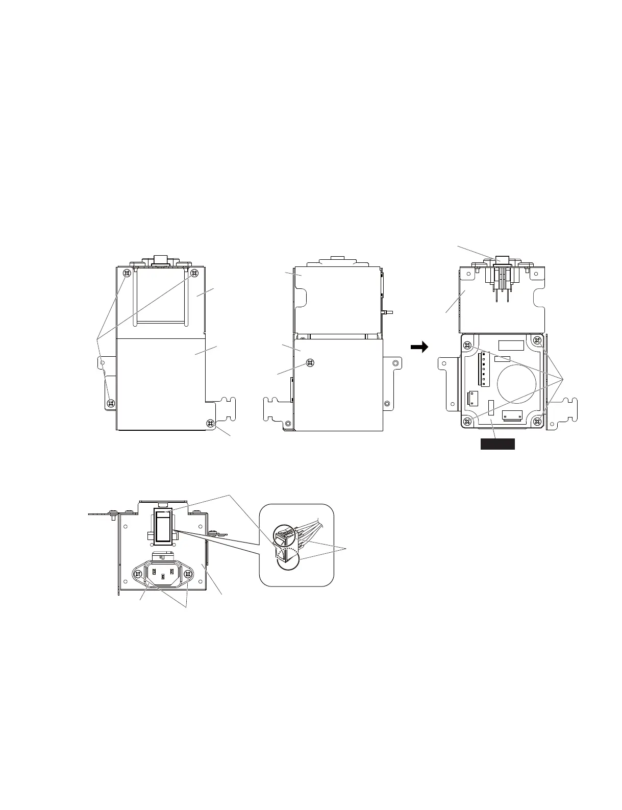
A-12-9 AC Inlet Assembly
(Time required: About 12 minutes):
A-12-9-1
Remove the two (2) screws marked [40]. The AC inlet
assembly can then be removed. (Fig. 8)
A-12-10 PSW Connector Assembly
(Time required: About 12 minutes):
A-12-10-1
Hold down the claws of the PSW connector assembly
from inside, and remove the PSW connector assembly
from the outside of the AC shield bottom. (Fig. 8)
A-12-9 インレット Ass'y
(所要時間:約 12 分)
:
A-12-9-1
[40] のネジ 2 本を外して、インレット Ass'y を外
します。(図 8)
A-12-10
PSW 束線
(所要時間:約 12 分)
:
A-12-10-1
PSW 束線のツメを押さえながら、PSW 束線を
AC シールドボトムの外側から引き抜きます。
(図8)
Fig. 8
(図8)
 Loading...


