QL5/QL1
52
A-13. DCM Circuit Board
(Time required: About 15 minutes)
A-13-1
Remove the side pad assembly L and R. (See Procedure 1)
A-13-2 Fix the control panel S assembly. (See procedure 2)
A-13-3 Remove the DA circuit board. (See procedure A-6)
A-13-4 Remove the JK circuit board assembly.
(See procedure A-7)
A-13-5 Remove the power supply unit. (See procedure A-8)
A-13-6 Remove the four (4) screws marked [300]. The power
angle bottom can then be removed. (Fig. 7)
* When installing the power angle bottom, tighten the
screws
a
to
d
shown in fig. 7 in numerical order.
A-13-7 Remove the AC S assembly. (See procedure A-11)
A-13-8 Remove the screw marked [190]. The L angle S can
then be removed. (Fig. 7)
A-13-9 Remove the eight (8) screws marked [170]. The DCM
circuit board can then be removed. (Fig. 7)
* When installing the DCM circuit board, tighten the
screws
q
,
w
shown in fig. 7 in numerical order.
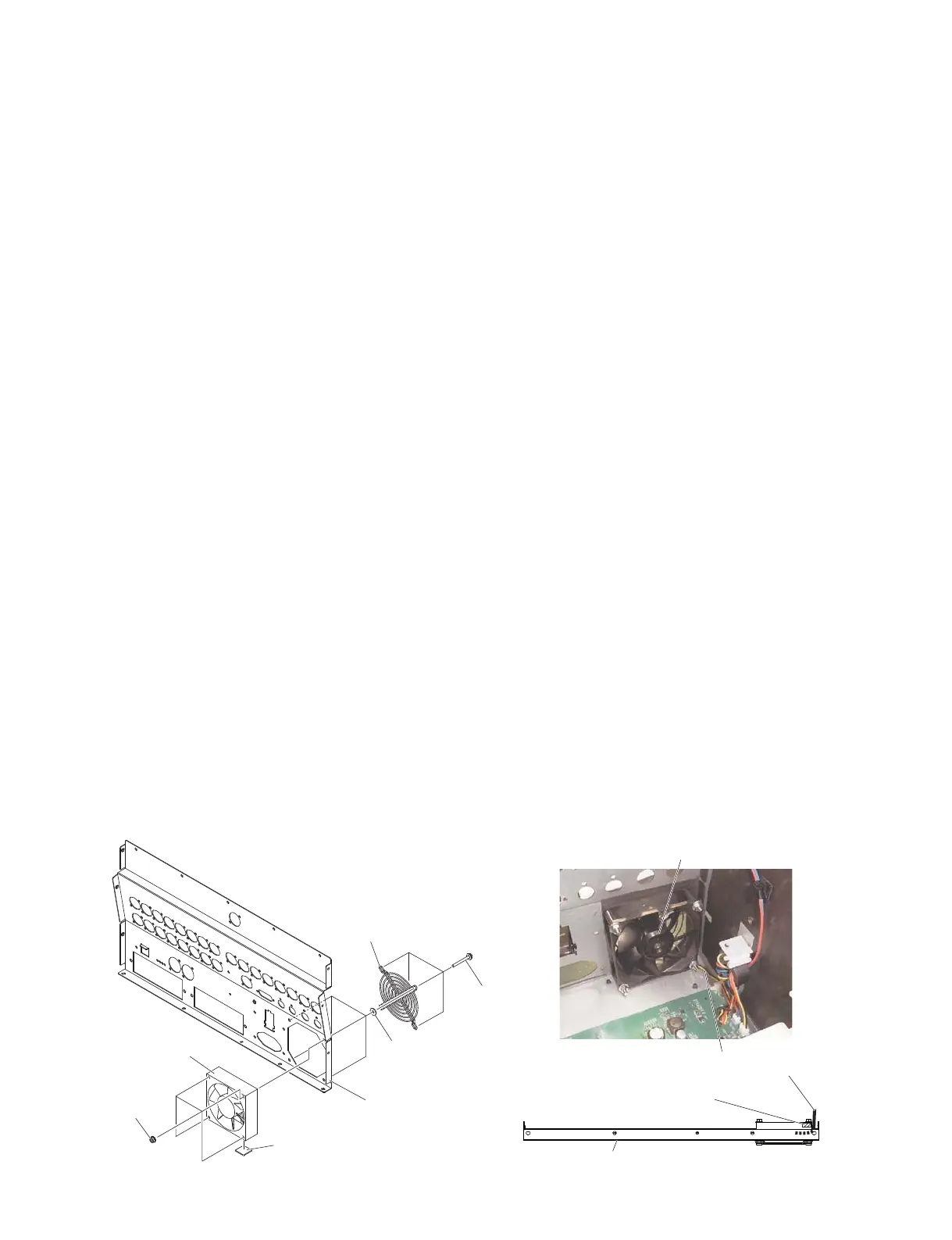
A-14. DC Fan Motor
(Time required: About 12 minutes)
A-14-1
Remove the side pad assembly L and R. (See Procedure 1)
A-14-2 Fix the control panel S assembly. (See procedure 2)
A-14-3 Remove the DA circuit board. (See procedure A-6)
A-14-4 Remove the JK circuit board assembly.
(See procedure A-7)
A-14-5 Remove the AC S assembly. (See procedure A-11)
A-14-6 Remove the four (4) screws marked [20e], the four (4)
plain washers marked [20f] and the four (4) hexagonal
flange nuts marked [20g]. The finger guard and DC
fan motor the can then be removed. (Fig. 9)
* When installing the DC fan motor, pass the fan
connector assembly through the space between the
rubber sponge spacer and rear S assembly. Secure
the assembly firmly so that it does not bend and get
caught in the fan. (Photo 9)
A-13. DCM シート
(所要時間:約 15 分)
A-13-1 サイドパッド Ass'yL,R を外します。(1 項参照)
A-13-2 コンパネ SAss'y を固定します。(2 項参照)
A-13-3 DA シートを外します。(A-6 項参照)
A-13-4 JK シート Ass'y を外します。(A-7 項参照)
A-13-5 電源ユニットを外します。(A-8 項参照)
A-13-6 [300] のネジ 4 本を外して、パワーアングルボト
ムを外します。(図 7)
※ パワーアングルボトムを取り付ける際は、図 7に示す
a
→
d
の順にネジを締めてください。
A-13-7 ACSAss'y を外します。(A-11 項参照)
A-13-8 [190] のネジ 1 本を外して、LアングルSを外し
ます。(図 7)
A-13-9 [170] のネジ 8 本を外して、DCM シートを外し
ます。(図 7)
※ DCM シートを取り付ける際は、図 7に示す
q
、
w
の
順にネジを締めてください。
A-14. DC ファンモーター
(所要時間:約 12 分)
A-14-1 サイドパッド Ass'yL,R を外します。(1 項参照)
A-14-2 コンパネ SAss'y を固定します。(2 項参照)
A-14-3 DA シートを外します。(A-6 項参照)
A-14-4 JK シート Ass'y を外します。(A-7 項参照)
A-14-5 ACSAss'y を外します。(A-11 項参照)
A-14-6 [20e] のネジ 4 本と [20f] の平座金みがき丸 4 枚と
[20g] のナット6角フランジ 4 個を外して、フィ
ンガーガードとともに DC ファンモーターを外
します。(図 9)
※ ファンモーターを取り付ける際は、ファン束線をスポ
ンジスペーサーとリア SAss'y の間を通します。たわ
んでファンに巻き込まれないようにしっかりと固定し
てください。(図 9)
REAR S ASSEMBLY
(リア SAssy)
REAR S ASSEMBLY
(リア SAssy)
<Bottom view(底面)>
[20e]
[20f]
[20g]
FINGER GUARD
(フィンガーガード)
RUBBER SPONGE SPACER
(スポンジスペーサー)
RUBBER SPONGE SPACER
(スポンジスペーサー)
DC FAN MOTOR
(DC ファンモーター)
DC FAN MOTOR
(DCファンモーター)
FAN CONNECTOR ASSEMBLY
(ファン束線)
Fig. 9
(図9)
 Loading...


