QL5/QL1
53
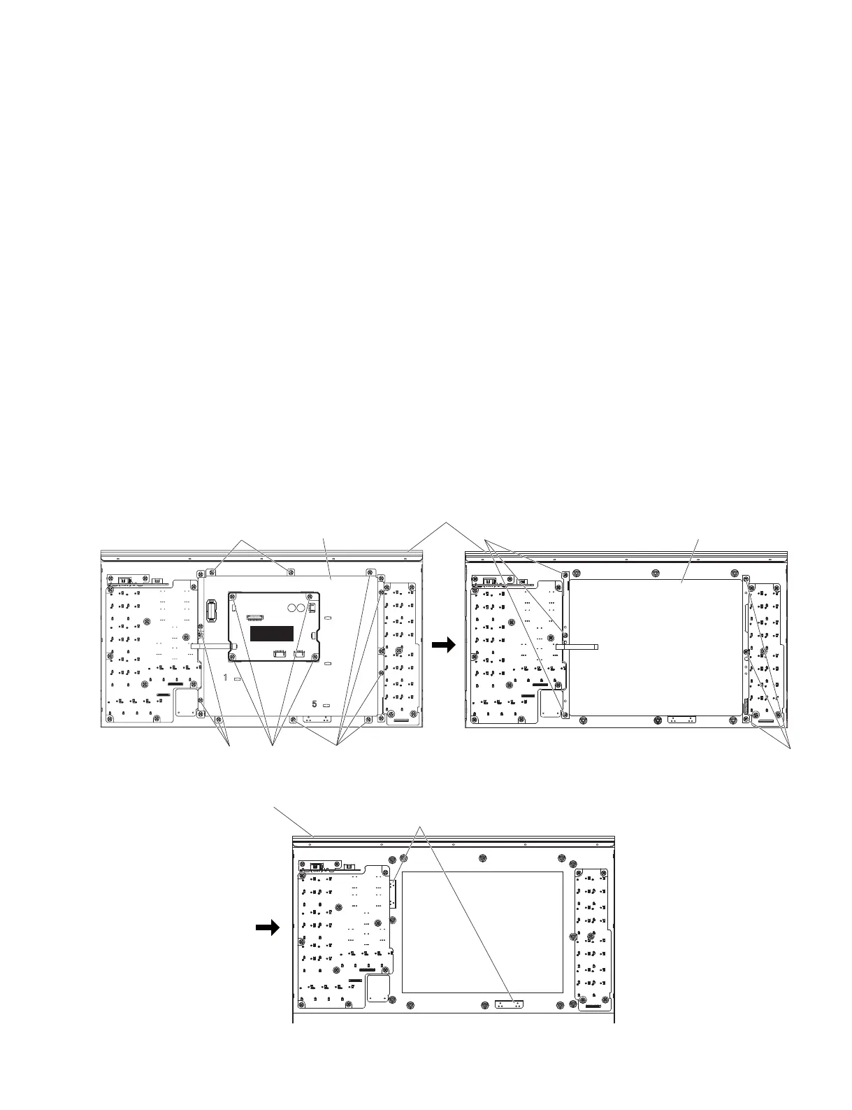
Fig. 10
(図10)
B. コンパネ SAss'y 部の分解
B-1. LCDC シート
(所要時間:約 6 分)
B-1-1 サイドパッド Ass'yL,R を外します。(1 項参照)
B-1-2 コンパネ SAss'y を外します。(2 項参照)
B-1-3 [310] のネジ 4 本を外して、LCDC シートを外し
ます。(図 10)
B-2. LCDAss'y
(所要時間:約 8 分)
B-2-1 サイドパッド Ass'yL,R を外します。(1 項参照)
B-2-2 コンパネ SAss'y を外します。(2 項参照)
B-2-3 [320] のネジ 10 本を外して、LCD シールドケー
スを外します。(図 10)
B-2-4 [190] のネジ 6 本を外して、LCD Ass'y を外しま
す。(図 10)
※ LCDAss'y を取り付ける際は、図 10に示すパネルの
金具に当て付けてから、ネジを締めてください。
B. Disassembly Procedure of Control
panel S Assembly
B-1. LCDC Circuit Board
(Time required: About 6 minutes)
B-1-1
Remove the side pad assembly L and R. (See Procedure 1)
B-1-2
Remove the control panel S assembly. (See procedure 2)
B-1-3 Remove the four (4) screws marked [310]. The LCDC
circuit board can then be removed. (Fig. 10)
B-2. LCD Assembly
(Time required: About 8 minutes)
B-2-1
Remove the side pad assembly L and R. (See Procedure 1)
B-2-2
Remove the control panel S assembly. (See procedure 2)
B-2-3 Remove the ten (10) screws marked [320]. The LCD
shield case can then be removed. (Fig. 10)
B-2-4 Remove the six (6) screws marked [190]. The LCD
assembly can then be removed. (Fig. 10)
* When installing the LCD assembly, be sure to apply
it to the metal part of the panel shown in fig. 10 and
then tighten the screw.
[310]
[320]
[320]
LCDC
LCD SHIELD CASE
(LCD シールドケース)
CONTROL PANEL S ASSEMBLY
(コンパネ SAss'y)
[320]
LCD ASSEMBLY
(LCDAss'y)
CONTROL PANEL S ASSEMBLY
(コンパネ SAss'y)
METAL PART
(金具)
[190]
[190]
<Bottom view(底面)>
 Loading...


