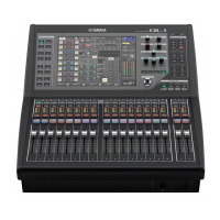
QL5/QL1
56
B-6. USB Circuit Board
(Time required: About 6 minutes)
B-6-1
Remove the side pad assembly L and R. (See Procedure 1)
B-6-2
Remove the control panel S assembly. (See procedure 2)
B-6-3 Remove the two (2) screws marked [360A]. The
USB fi xed angle and USB circuit board can then be
removed. (Fig. 11)
* When installing the USB Circuit Board, tighten the
screws
q
,
w
shown in fig. 11 in numerical order.
B-6-4 Remove the two (2) screws marked [360B]. The USB
circuit board can then be removed. (Fig. 11)
* When installing the USB fixed angle, tighten the
screws
A
,
B
shown in fig. 11 in numerical order.
B-7. FD1M Circuit Board (CH1-16)
(Time required: About 10 minutes)
B-7-1
Remove the side pad assembly L and R. (See Procedure 1)
B-7-2
Remove the control panel S assembly. (See procedure 2)
B-7-3 Remove the sixteen (16) fader knobs N marked [490]
from the control panel side. (Fig. 14)
B-7-4 Remove the twelve (12) screws marked [140]. The
FD1M circuit board can then be removed. (Fig. 14)
B-8. FD1S Circuit Board (MASTER A, B)
(Time required: About 7 minutes)
B-8-1
Remove the side pad assembly L and R. (See Procedure 1)
B-8-2
Remove the control panel S assembly. (See procedure 2)
B-8-3 Remove the two (2) fader knobs NR marked [500]
from the control panel side. (Fig. 14)
B-8-4 Remove the four (4) screws marked [150]. The FD1S
circuit board can then be removed. (Fig. 14)
B-9. PN16M Circuit Board
(Time required: About 8 minutes)
B-9-1
Remove the side pad assembly L and R. (See Procedure 1)
B-9-2
Remove the control panel S assembly. (See procedure 2)
B-9-3 Remove the four (4) screws marked [110]. The two (2)
PN push angle 8 can then be removed. (Fig. 14)
B-9-4 Remove the ten (10) screws marked [60]. The PN16M
circuit board can then be removed. (Fig. 14)
* The PN16M circuit board contains the following
buttons (Fig. 15)
· [20]: Button L (LARGE) 4P (SEL) 4 pc.
· [30]: Button S (SMALL) 4P (CUE) 4 pc.
· [40]: Button L (LARGE) 4P (ON) 4 pc.
B-6. USB シート
(所要時間:約 6 分)
B-6-1 サイドパッド Ass'yL,R を外します。(1 項参照)
B-6-2 コンパネ SAss'y を外します。(2 項参照)
B-6-3 [360A] の ネジ 2 本を外して、USB 固定金具と
USB シートを外します。(図 11)
※ USB シートを取り付ける際は、図 11 に示す q、w の
順にネジを締めてください。
B-6-4 [360B] のネジ 2 本を外して、USB 固定金具を外
します。(図 11)
※ USB 固定金具を取り付ける際は、図 11 に示す
A
、
B
の順にネジを締めてください。
B-7. FD1M シート(CH1 〜 16)
(所要時間:約 10 分)
B-7-1 サイドパッド Ass'yL,R を外します。(1 項参照)
B-7-2 コンパネ SAss'y を外します。(2 項参照)
B-7-3 コントロールパネル面より、[490] のフェーダー
ノブ N16 個を外します。(図 14)
B-7-4 [140] のネジ 12 本を外して、FD1M シートを外
します。(図 14)
B-8. FD1S シート(MASTERA,B)
(所要時間:約 7 分)
B-8-1 サイドパッド Ass'yL,R を外します。(1 項参照)
B-8-2 コンパネ SAss'y を外します。(2 項参照)
B-8-3 コントロールパネル面より、[500] のフェーダー
ノブ NR2 個を外します。(図 14)
B-8-4 [150] のネジ 4 本を外して、FD1S シートを外し
ます。(図 14)
B-9. PN16M シート
(所要時間:約 8 分)
B-9-1 サイドパッド Ass'yL,R を外します。(1 項参照)
B-9-2 コンパネ SAss'y を外します。(2 項参照)
B-9-3 [110] のネジ 4 本を外して、PNPUSH 金具 8 2
個を外します。(図 14)
B-9-4 [60] のネジ 10 本を外して、PN16M シートを外
します。(図 14)
※ PN16M シートには、下記のボタンがついています。
(図 15)
・[20]:ボタン(大)4 連 (SEL) 4 個
・[30]:ボタン(小)4 連 (CUE) 4 個
・[40]:ボタン(大)4 連 (ON) 4 個

 Loading...