ENGINE
TNV IDI Service Manual
6-57
Cylinder Block
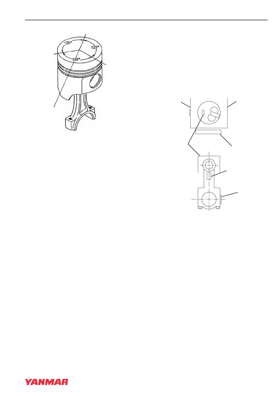
1 –Top Compression Ring End Gap
2 –Second Compression Ring End Gap
3 –Oil Ring End Gap
Figure 6-92
IMPORTANT
Ensure piston ring gaps are located
correctly (Figure 6-92).
3. Using a piston ring compressor, compress the
piston rings.
IMPORTANT
The piston and connecting rod must be
reinstalled with the correct orientation.
When installed correctly, the identification
mark (Figure 6-93, (2)) stamped into the
top of the piston will be on the same side of
the engine as the fuel injection pump
(Figure 6-93, (1)) and the embossed mark
(Figure 6-93, (3)) cast into the connecting
rod beam will face the flywheel end of the
engine (Figure 6-93, (5)).
4. Carefully reinstall the piston and rod assembly.
Be sure the match marks (Figure 6-93, (4))
stamped into the connecting rod and cap are
facing the fuel injection pump side of the
cylinder block, and the piston identification
mark (Figure 6-93, (2)) stamped into the piston
top is facing the camshaft side
(Figure 6-93, (6)). The embossed mark cast
into the connecting rod beam (Figure 6-93, (3))
will be facing the flywheel end of the engine
(Figure 6-93, (5)).
1 –Fuel Injection Pump Side of Engine
2 –Piston Identification Mark
3 –Embossed Mark on Connecting Rod
4 –Rod and Cap Match Marks
5 –Flywheel End of Engine
6 –Camshaft Side of Engine
Figure 6-93
5. Reinstall the bearing inserts (Figure 6-94, (1))
in the connecting rod and cap.
6. Apply a liberal coat of clean engine oil to the
bearing inserts and crankshaft journal.
0000226A
(2)
(1)
(3)
0000227A
(1)
(6)
(5)
(4)
(3)
(2)
TNV_IDI_ServiceManual_A4.book 57 ページ 2012年2月24日 金曜日 午前10時24分