SYSTEM DIAGRAMS
JH Series Operation Manual 137
12/05
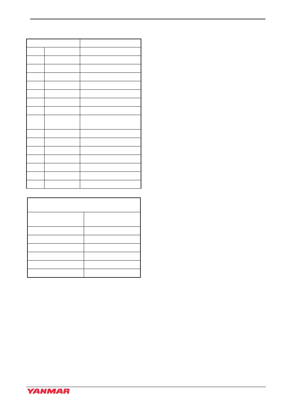
WIRING DIAGRAMS
Color Coding Engine Harness
RRed +
BBlack -
W White Ignition
L Blue Air Heater / Glow (option)
RB Red / Black Alternator Exciter
LB Blue / Black Alternator Charge Alarm
YW Yellow / White Engine Oil Pressure Alarm
YB Yellow / Black Engine Oil Pressure
YG Yellow /
Green
Sail Drive Seal
WL White / Blue Water Temperature Alarm
WB White / Black Water Temperature
V Purple ACC Power
BW Blue / White Fuel Tank Level
GR Green / Red Fuel filter alarm
O Orange Pulse for Tachometer
WBr White / Brown Electric Stop
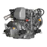
Allowable Length by Cross Sectional Area of
Battery Cable
Section of Cable
mm
2
(in.
2
)
Allowable Length
L = 1 + 2 + 3 m (ft)
15 (0.023) < 0.86 (0.26)
20 (0.031) < 1.3 (0.40)
30 (0.046) < 2.3 (0.70)
40 (0.062) < 2.8 (0.85)
50 (0.077) < 3.5 (1.07)
60 (0.093) < 4.1 (1.25)
JH5_EN_OPM.book 137 ページ 2013年8月8日 木曜日 午前9時23分