1-18
TERMINAL FUNCTIONS LEVELS
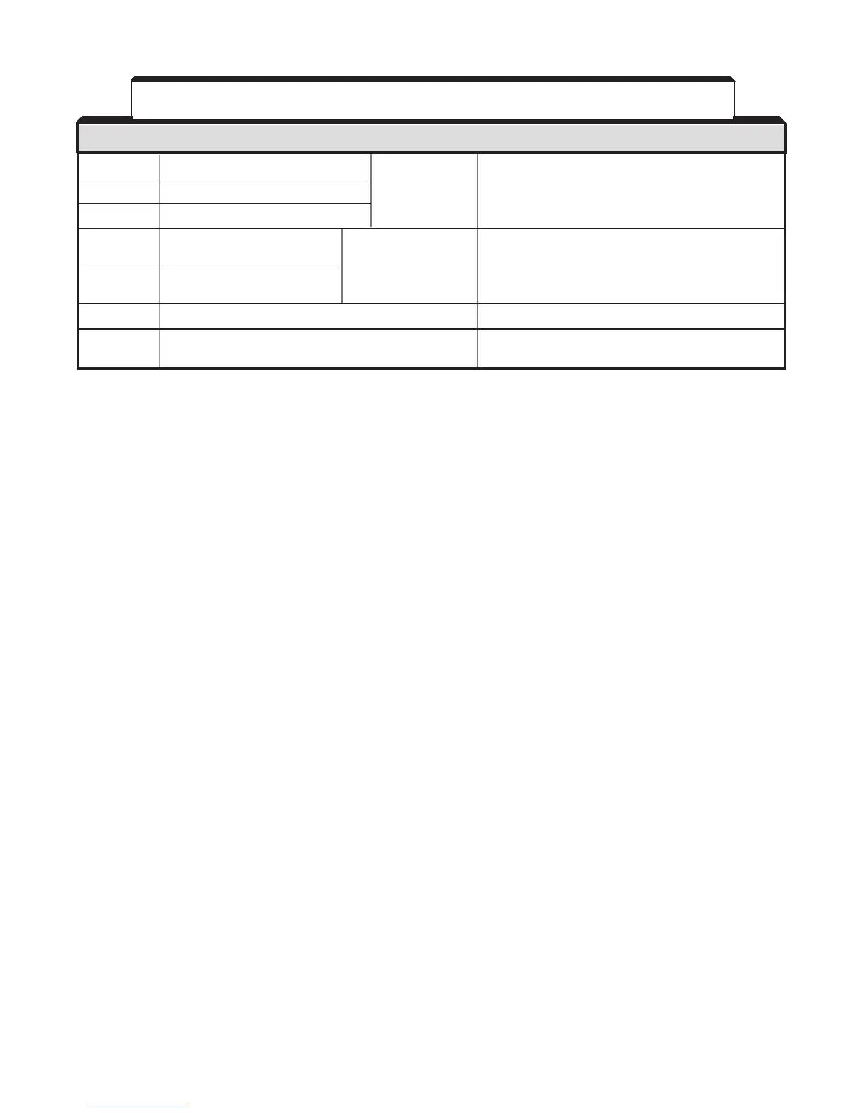
21 Multi-function analog monitor 1 (+) Output current Type of analog signal (operation parameter) to be
22 Multi-function analog monitor (–)
or output output is selected by setting of parameters H4-01
frequency is and H4-04 .
23 Multi-function analog monitor 2 (+) selectable Monitor output: 0 to +11V; 2 mA maximum
25 Multi-function open collector One of 18 functions Photocoupler insulation output: +48V, 50 mA
output 1 available, by setting maximum
26 Multi-function open collector
of parameters H2-02
output 2
and H2-03 .
27 Multi-function open collector output common 0V
33 Frequency reference power supply –15V Control power supply for frequency setting:
max 20 mA
TERMINAL FUNCTIONS DESCRIPTION / SIGNAL LEVELS
NOTES:
1 . When Forward Run and Reverse Run inputs are both closed for more than 500 ms, the Digital
Operator displays a blinking “ EF ” alarm code and the motor (if rotating) is decelerated by the
drive to a stop. This stop condition is not stored by the drive (on Digital Operator, red LED at
S T O P key does not light); IF O NE OF THE INPUTS IS OPEN ED, T HE MO TOR W ILL
I M M E D I A T E L Y S T A R T U P A G A I N .
2 . Terminals 1-8 source +24 Vdc (8mA max.) and operate in a Low = True (ON) configuration when
connected to terminal 11.
When using relays for input to terminals 1-8, use relays with highly reliable contacts (for very
small current) with a capacity of 30 Vdc or more and rated current of 100mA or higher. When
using transistor (open collector) input, use transistors with rated voltage of 35 Vdc or more and
rated current of 100mA or more.
3 . These terminals are multi-function inputs. The indicated functions are their settings, based on a
2-Wire reset. For 3-Wire reset definitions, and other settings, see descriptions for “Multi-
Function Input Terminals”, parameters H 1 - 0 1 th r u H 1 - 0 6 , in paragraph 5.32.
Table 1-3. Terminal Functions and Signals of Control Circuit - Continued
 Loading...


