YASKAWA TM.iQp.02 iQpump Drive Programming Manual 13
Figure 1.6
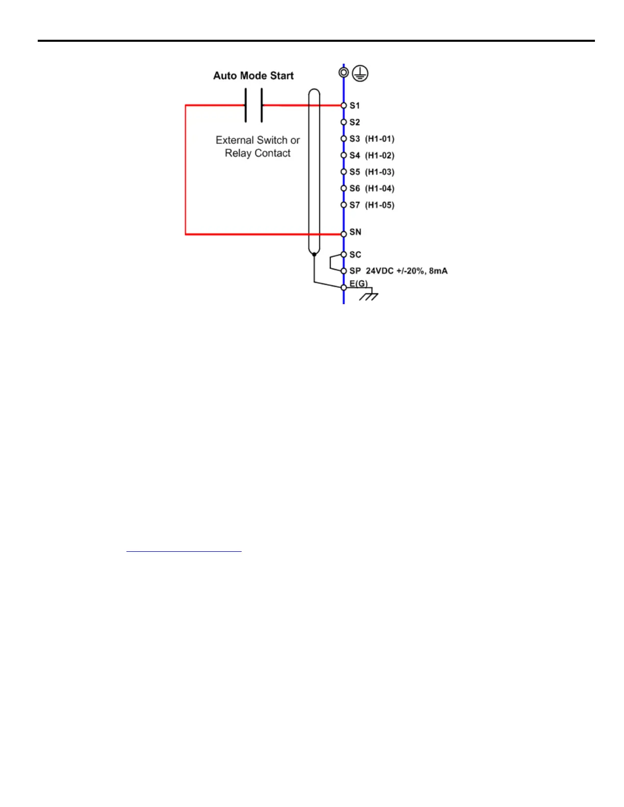
Figure 6 Connection Diagram of External Start/Stop Switch
If the Run command is determined by Serial Communications: b1-02 = “2: Serial Communications,” and initiate the Run command
through the serial communications. Refer to Figure 6 (in the previous b1 sequence section) for the connection diagram for serial
communications through the RS232/485 terminals. The following is a simple setup procedure for programming the iQpump drive and PC
Serial communications to initiate Run and Stop commands through serial communications.
1. Program b1-02 = “2: Serial communications”.
2. Program the following H5 parameters:
H5-01 Serial Communication Address: 31
H5-02 Serial Baud Rate: 9600 Baud (setting 3).
H5-03: Serial Communication Parity Selection: None (setting 0)
3. Initiate a Start/Stop command
iQpump command register number: 0001
Stop Command: Transmit value of 0000 (16 bit) to iQpump command address.
Start Command: Transmit value of 0001 (16 bit) to iQpump command address.
Reset Command: Transmit value of 0008 (16 bit) to iQpump command address.
If the Run command input is determined by a network communications option PCB: b1-02 = “3: Option PCB,” and initiate the Run
command through the available network communications option PCB listed below. The Installation Guides (IG) and Technical Manuals
(TM) are available at http://iQpump.yaskawa.com
.
The iQpump Controller allows for monitoring, diagnostics and control using any of the following communication option cards:
Note: Refer to the communication card instruction manual or consult factory for installation and operation instructions.
■ Start/Stop from Comm. Option Card (Parameter b1-01 = 3):
The iQpump Controller allows for the setpoint reference to be set via any of the following communication option cards:
• Profibus DP Option Card CM061 Manual: IG.AFD.12
• DeviceNet Option Card CM05X Manual: IG.AFD.14
• Modbus Plus Option Card CM071 Manual: IG.AFD.17
• Modbus TCP/IP Option Card CM090 Manual: IG.AFD.25
• EtherNet/IP Option Card CM092 Manual: IG.AFD.26
• Profibus DP Option Card CM061 Manual: IG.AFD.12
• DeviceNet Option Card CM05X Manual: IG.AFD.14
b1-02 = 1
b
b1-02 = 1

 Loading...


