3 Electrical Installation
YASK AWA TOEPYAIL1E01A YASKAWA AC Drive L1000E Quick Start Guide 43
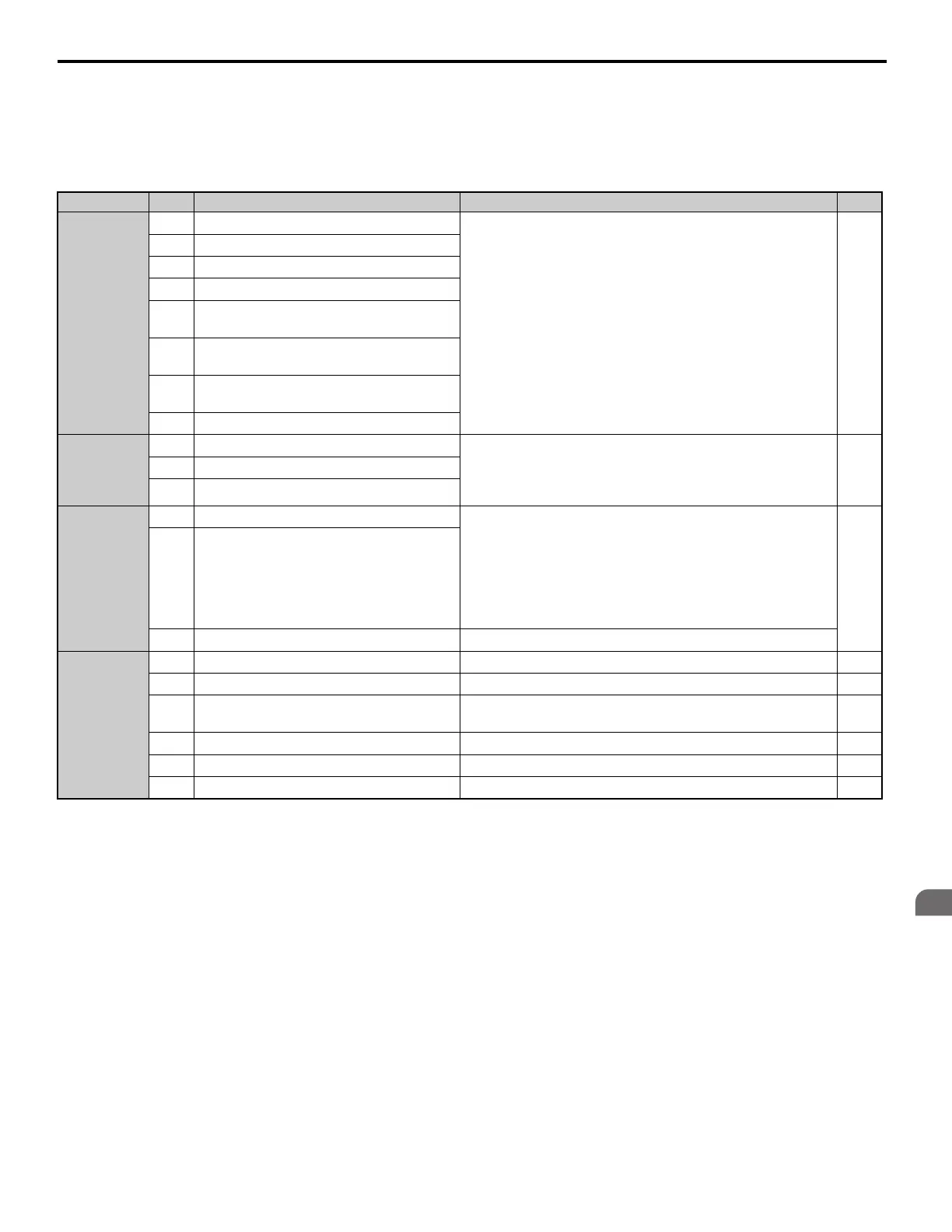
Input Terminals
Table 11 lists the input terminals on the drive. Text in parenthesis indicates the default setting for each multi-function
input.
Table 11 Control Circuit Input Terminals
Type
<1> Setting jumper S3 for an external power supply makes the wire jumper between terminals H1, H2, and HC ineffective. Remove the wire jumper
and connect an external power supply that can supply terminals H1, H2, and HC continuously.
No. Terminal Name (Function) Function (Signal Level) Default Setting Page
Digital Inputs
S1
Up Command (Closed: Up, Open: Stop)
Photocoupler
24 Vdc, 8 mA
Use the wire link between terminals SC and SN or between SC
and SP to select sinking or sourcing, and to select the power
supply.
180
S2
Down Command (Closed: Down, Open: Stop)
S3
Multi-function input 1 (External Fault)
S4
Multi-function input 2 (Fault Reset)
S5
Multi-function input 3 (Multi-Step Speed
Reference 1)
S6
Multi-function input 4 (Multi-Step Speed
Reference 2)
S7
Multi-function input 5 (Multi-Step Speed
Reference 3)
S8
Multi-function input 6 (Not used)
Digital Input
Power Supply
SC
Multi-function input common
24 Vdc, 150 mA (only when DI-A3 is not used)
Use the wire jumper between terminals SC and SN or between SC
and SP to select sinking or sourcing, and to select the power
supply.
49
SN
0 V
SP
+24 Vdc
Safe Disable
Inputs <1>
H1
Safe Disable input 1
24 Vdc, 8 mA
One or both open: Drive output disabled
Both closed: Normal operation
Internal impedance: 3.3 kΩ
Off time of at least 1 ms
Set the S3 jumper to select sinking or sourcing, and to select the
power supply.
230
H2
Safe Disable input 2
HC
Safe Disable function common Common for the Safe Disable function
Analog Inputs
+V
Power supply for analog inputs 10.5 Vdc (max allowable current 20 mA) 228
-V
Power supply for analog inputs -10.5 Vdc (max allowable current 20 mA) –
A1
Multi-function analog input 1 (Speed
reference bias)
-10 to 10 Vdc, 0 to 10 Vdc (input impedance: 20 kΩ)–
A2
Multi-function analog input 2 (Not used) -10 to 10 Vdc, 0 to 10 Vdc (input impedance: 20 kΩ)–
AC
Analog input common 0 V –
E (G)
Ground for shielded lines and option cards – –