3 Electrical Installation
YASK AWA TOEPYAIL1E01A YASKAWA AC Drive L1000E Quick Start Guide 45
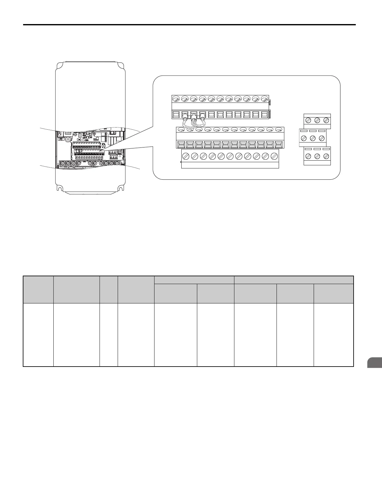
■ Terminal Configuration
Control circuit terminals are arranged as shown in Figure 25.
Figure 25
Figure 25 Control Circuit Terminal Arrangement
Wire Size and Torque Specifications
WARNING! Fire hazard. Tighten all terminal screws to the specified tightening torque. Loose electrical connections could result in
death or serious injury by fire due to overheating of electrical connections. Improperly tightened terminal screws can also cause
erroneous equipment operation.
Select appropriate wire type and gauges from Table 14. For simpler and more reliable wiring, use crimp ferrules on the
wire ends. Refer to Table 15 for ferrule terminal types and sizes.
Table 14 Wire Gauges and Torque Specifications
Terminal
Block
Terminal Size
Tightening
Torque
Nm
(lb.in.)
Bare Wire Terminal Ferrule-Type Terminal
Applicable
Wire Size
mm
2
(AWG)
Recomm.
mm
2
(AWG)
Applicable
Wire Size
mm
2
(AWG)
Recomm.
mm
2
(AWG)
Wire Type
TB1, TB2,
TB4, TB5,
TB6
FM, AC, AM, P1,
P2, PC, SC, A1,
A2, A3, +V, -V,
S1-S8, MA, MB,
MC, M1, M2, HC,
H1, H2, DM+,
DM-, IG, R+, R-,
S+, S-, RP, MP, E
(G)
M2
0.22 to 0.25
(1.9 to 2.2)
Standard wire:
0.25 to 1.0
(24 to 17)
Solid wire:
0.25 to 1.5
(24 to 16)
0.75
(18)
0.25 to 0.5
(24 to 20)
0.5
(20)
Shielded wire,
etc.
E(G) HC H1 H2
DM+ DM-
IG R+ R- S+ S-
S1 S2 S3 S4 S5 S6 S7 S8 SN SC SP
V+ AC V- A1
A2
FM AM AC P1 C1 C2P2
M3 M4 M6
MA MB MC
M1 M2 M5