Do you have a question about the YASKAWA MA1440 and is the answer not in the manual?
Safety warnings and symbols used in the manual for hazard communication.
Definitions of terms used throughout the manual for clarity and consistency.
Identifies the intended audience and their required knowledge for understanding the manual.
Lists the typical applications and purposes for which the robot is designed.
Details forbidden operations and potential consequences to prevent misuse.
Explains the manual's content, scope, and how to use it effectively.
Provides critical safety information, warnings, and precautions for operation.
Information about the robot manufacturer, YASKAWA ELECTRIC CORPORATION.
Details of the authorized representative, YASKAWA Europe GmbH.
Lists all items included in the standard delivery package for the robot system.
Information on verifying serial numbers on the robot and controller type plates.
General precautions and methods for safely transporting the robot.
Instructions for safely lifting and moving the robot using a crane.
Guidelines for transporting the robot securely with a forklift.
Details on using shipping brackets and bolts for secure transport.
Essential safety measures and protective devices required for robot installation.
Environmental requirements for temperature, humidity, and installation site.
Step-by-step guide and diagrams for mounting the robot base to the floor.
Requirements and procedures for proper electrical grounding of the robot system.
Instructions for connecting the robot and controller cables.
Specific steps for connecting the encoder and power cables to the robot.
How to connect the robot cables to the robot controller unit.
Steps for connecting the programming pendant cable to the controller.
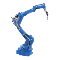
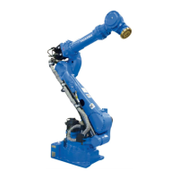
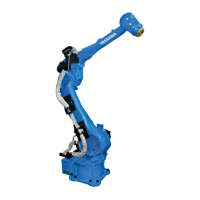
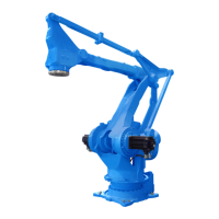
Identification of robot components and axis labels for reference.
Provides detailed dimensional specifications for the robot's base.
Details robot dimensions and its defined operational workspace.
Information on how to adjust and configure the robot's movement limits.
Lists components required for adjusting the S-axis working range.
Steps for installing mechanical limits to restrict axis movement.
How to set pulse limits for S-axis movement to define its range.
Data on robot stopping behavior during emergency stops.
Stopping parameters for emergency stop category 0.
S-axis stopping data for emergency stop category 0.
L-axis stopping data for emergency stop category 0.
U-axis stopping data for emergency stop category 0.
Stopping parameters for emergency stop category 1.
S-axis stopping data for emergency stop category 1.
L-axis stopping data for emergency stop category 1.
U-axis stopping data for emergency stop category 1.
Dimensions and specifications for the robot's wrist flange mounting.
Information on the maximum load capacity and inertia for the S-axis.
Guidelines for achieving optimal performance through load management.
Specifies allowable torque and moment of inertia for wrist axes.
Details maximum load limits for U-axis and S-axis including inertia.
Description of internal wiring harnesses, air lines, and their connections.
Outlines required inspection intervals, methods, and responsible personnel.
Information and precautions related to the robot's battery unit.
Step-by-step guide for replacing the battery pack in the robot controller.
Details on battery pack connectors and associated safety warnings.
General notes and precautions for performing robot maintenance.
Instructions for refilling or replacing grease in robot components.
Specifics on greasing the S, L, and U axes, including amounts.
Specifics on greasing the R, B, and T axes, including amounts.
Procedures for calibrating and setting the robot's home position.
Method to calibrate all robot axes simultaneously.
Method to calibrate each robot axis separately.
Instructions on how to modify absolute encoder data after calibration.
Procedure to reset and clear absolute encoder data.
How to set an alternative home position for verification and error checking.
Explains the objective and necessity of the position check operation.
Step-by-step guide to set the second home position for the robot.
Steps to follow after specific alarms occur during operation.
Optional function for automatically restoring initial robot data.
Diagram showing connections for the zeroing device and related components.
Explanation of the YasXzero device, its elements, and operation.
General procedure for resetting the robot's zero position.
Steps to take and precautions before performing a reset operation.
Detailed steps for resetting a specific robot axis using the zeroing function.
Illustrates the mounting positions for reset sensors on robot axes.
Troubleshooting guide for common errors encountered during resetting.
Lists recommended spare parts for the robot, including motors and gears.
Lists recommended spare parts for the robot controller and its modules.
Detailed parts breakdown and diagrams for the robot's S-axis.
Detailed parts breakdown and diagrams for the robot's L-axis.
Detailed parts breakdown and diagrams for the robot's U-axis.
Detailed parts breakdown and diagrams for the robot's R-axis.
Detailed parts breakdown and diagrams for the robot's wrist unit.