
М
МатвейApr 15, 2026
Здравствуйте, подскажите пожалуйста, как скачать полную документацию на определенных роботов
Здравствуйте, подскажите пожалуйста, как скачать полную документацию на определенных роботов
Important safety instructions for operating the Yaskawa robot.
Glossary of common terms used in the manual.
Defines the intended audience and required knowledge for this manual.
Describes the typical applications and purposes of the robot.
Outlines impermissible uses and potential consequences.
Provides information about the manual's content and scope.
Crucial safety warnings and precautions for robot operation.
Details about the robot manufacturer, Yaskawa Electric Corporation.
Information on the authorized representative in Europe.
Instructions for verifying the delivered robot system components.
Guidance on identifying the robot and controller using type plates.
Procedures and precautions for safely transporting the robot.
Details on using shipping brackets and bolts for secure transport.
Information on damping materials used for safe robot transportation.
Essential safety measures and protective devices for robot installation.
Specifies environmental conditions and location requirements for robot installation.
Practical demonstration and steps for installing the robot.
Electrical installation standards and regulations for proper grounding.
Instructions for connecting robot cables to the controller and pendant.
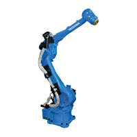
Identification of robot parts and designation of work axes.
Detailed dimensions and mounting points of the robot base.
Specifications for robot dimensions and its operational working envelope.
Information on adjusting the robot's S-axis working range.
Data on robot stopping performance during emergency stops.
Dimensions and specifications for the robot's wrist flange.
Maximum allowable load and moment of inertia for the robot's wrist.
Detailed list of parts for the robot's S-axis.
Detailed list of parts for the robot's L-axis.
Parts list for the robot's R, B, and T axes drives.
Detailed list of parts for the robot's U-arm unit.
Detailed list of parts for the robot's wrist unit.
| Payload Capacity | 180 kg |
|---|---|
| Reach | 2702 mm |
| Degrees of Freedom | 6 |
| Axes | 6 |
| Installation | Indoor |
| Mounting | Floor |
| Protection Class | IP54 |