Do you have a question about the YASKAWA Motoman UP6 and is the answer not in the manual?
Provides general information about the manual's structure, reference documents, and customer service details.
Provides contact details for technical assistance and required information for service calls.
Emphasizes the importance of obtaining and reviewing safety standards for industrial robots.
Explains safety signal words (DANGER, WARNING, CAUTION, NOTE) used throughout the manual.
Offers programming tips to ensure safe robot operation and prevent warranty voiding modifications.
Details standard items to check upon package arrival and special care for multiple manipulator installations.
Outlines procedures for using cranes or forklifts for safe manipulator transportation.
Details lifting the manipulator using wire rope threaded through eyebolts and fixing with jigs.
Emphasizes the importance of installing safety guards to prevent accidents and equipment damage.
Details firm mounting on a baseplate/foundation to withstand repulsion forces during acceleration/deceleration.
Provides instructions on following local regulations for grounding line size and proper grounding methods.
Explains connecting power and signal cables between the manipulator base and the XRC.
Presents detailed specifications including operation mode, payload, motion range, and maximum speed.
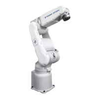
Illustrates and names the different parts and working axes of the manipulator.
Specifies the allowable wrist load and force limits for R-, B-, and T-Axes.
Outlines conditions for attaching peripheral equipment to the U-axis, including allowable load and installation position.
Illustrates the location of limit switches for S-, L-, and U-Axes.
Provides a schedule for proper inspections to ensure long-term functionality and safe operation.
Offers essential notes for maintenance procedures, including battery replacement and grease replenishment.
Lists recommended parts to stock as spares and provides a ranking system for them.
Provides a detailed list of parts for the S-Axis with DWG No., Name, and Pcs.
Details the parts list for the L.U-Axis driving unit with DWG No., Name, and Pcs.
Lists the technical specifications for the YASNAC XRC controller, including dimensions and power requirements.
Outlines the configuration of the XRC controller, including units and circuit boards.
Explains the cooling system mechanisms for maintaining optimal temperature within the controller.
Describes the components and function of the power supply unit in the XRC system.
Explains the operation methods for releasing the brake unit on the XRC controller.
Details routine inspections for the XRC controller, fans, emergency stop buttons, and battery.
Covers specific inspections for the YASNAC XRC, focusing on door closure and sealed construction.
Provides safety precautions and procedures for replacing XRC controller components like CPU rack components.
Details the procedure for replacing the disconnecting switch and its associated fuses.
Lists all replaceable parts for the YASNAC XRC, including model numbers and quantities.
Lists recommended spare parts for the XRC, categorized by rank (A, B, C).
Introduces the XRC controller's advanced functions and the importance of proper settings.
Explains the security system protecting XRC modes and user ID management.
Guides through essential system setup procedures like home position calibration and specified point settings.
Describes how to check the system CPU version information.
Covers checking the status of universal and specific input/output signals.
Lists the technical specifications for the YASNAC XRC controller, including dimensions and power requirements.
Lists available functions for programming pendant operation, safety features, and maintenance.
Explains the components and function of the power supply unit in the XRC system.
Details the configuration of the CPU rack, including circuit boards and power supply.
Describes the I/O contactor unit and its circuit boards for controlling servo power supply.
Outlines routine inspections for the XRC controller, fans, emergency stop buttons, and battery.
Provides safety precautions and procedures for replacing XRC controller parts like CPU rack components.
Details procedures for replacing the battery and the JANCD-XCP01 circuit board.
Lists all replaceable parts for the YASNAC XRC, including model numbers and quantities.
Lists recommended spare parts for the XRC, categorized by rank (A, B, C).
Classifies alarms by level (major/minor) and describes their reset methods.
Provides a comprehensive list of alarm messages, their causes, and recommended remedies.
Explains how errors are indicated and the procedure to release them.
Lists error codes related to system and general operations with their respective messages and contents.
| Type | Articulated Robot |
|---|---|
| Number of Axes | 6 |
| Payload Capacity | 6 kg |
| Repeatability | ± 0.1 mm |
| Mounting | Floor, Ceiling, Wall |




 Loading...