Do you have a question about the YASKAWA MOTOMAN-ES165D and is the answer not in the manual?
Defines DANGER, WARNING, CAUTION, MANDATORY, PROHIBITED terms and provides safety advice.
Highlights critical safety warnings related to maintenance and operation.
Verify the delivery contents, including manipulator, DX100, pendant, and cables.
Ensure the manipulator and DX100 share the same order number for proper function.
Guidelines for safely moving the manipulator, including weight and lifting.
Details on locating, using, and storing shipping bolts and brackets.
Importance of installing safeguarding to prevent accidents and equipment damage.
Instructions for securely mounting the manipulator base on a foundation.
Environmental conditions required for manipulator installation.
Procedures and requirements for proper electrical grounding of the manipulator.
Instructions for connecting manipulator cables to the base and DX100 controller.
Key technical specifications of the MOTOMAN-ES165D robot.
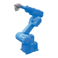
Identification of robot parts and the designation of its working axes.
Physical dimensions and mounting hole specifications for the manipulator base.
Graphical representation of robot reach and operational space.
Information on how to adjust the robot's axis operating limits.
Lists components required for modifying the S-axis operating range.
Guidance and precautions for installing mechanical stoppers to limit axis movement.
Steps to adjust pulse limitation for the S-axis to control its operating range.
Specifies the maximum payload and moment limits for the robot's wrist.
Dimensions and specifications for the robot's wrist flange.
Details on mounting points for external equipment on the robot arm.
Information on internal wiring and air lines for peripheral devices.
Explains the function and location of limit switches for axis operation ranges.
Details on how limit switches electrically limit axis operating ranges.
Identifies the physical placement of limit switches on the robot axes.
How to set operational ranges using limit switches for S-, L-, and U-axes.
Information on setting the S-axis operational range via limit switches.
Information on setting the L-axis operational range via limit switches.
How to set the interference angle range between L- and U-axes.
Diagrams and lists of internal connectors for maintenance and inspection.
Provides a schedule for routine inspections based on operating hours.
General guidelines and cautions for performing maintenance tasks.
Detailed procedures and precautions for greasing robot components.
Detailed breakdown and part numbers for the S-axis assembly.
Detailed breakdown and part numbers for the L-axis assembly.
Detailed breakdown and part numbers for the URBT-axes assembly.
Detailed breakdown and part numbers for the U-arm assembly.
Detailed breakdown and part numbers for the wrist assembly.
Detailed breakdown and part numbers for the balancer assembly.
| Model | MOTOMAN-ES165D |
|---|---|
| Type | Articulated Robot |
| Payload Capacity | 165 kg |
| Degrees of Freedom | 6 |
| Weight | 1280 kg |
| Controller | YRC1000 |
| Installation | Indoor |
| Protection Class | IP67 |
| Mounting | Floor |