EasyManua.ls Logo

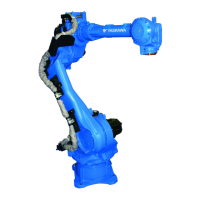
YASKAWA Motoman GP50 User Manual

YASKAWA Motoman GP50
109 pages
To Next Page IconTo Next Page
Page #1 background imageLoading...
Page #1 background image
MANUAL NO.
HW1484673
MOTOMAN-GP50,GP35L
MAINTENANCE MANUAL
TYPE:
YR-1-06VX50-A00
(MOTOMAN-GP50 STANDARD SPECIFICATION)
YR-1-06VXL35-A00
(MOTOMAN-GP35L STANDARD SPECIFICATION)
Procedures described in this maintenance manual should be carried out by the person who took
the maintenance-relevant trainings offered by YASKAWA.
Upon receipt of the product and prior to initial operation, read these instructions thoroughly, and
retain for future reference.
MOTOMAN INSTRUCTIONS
MOTOMAN-GP50,GP35L INSTRUCTIONS
YRC1000 INSTRUCTIONS
YRC1000 OPERATOR’S MANUAL (GENERAL) (SUBJECT SPECIFIC)
YRC1000 MAINTENANCE MANUAL
YRC1000 ALARM CODES (MAJOR ALARMS) (MINOR ALARMS)
The YRC1000 operators manual above corresponds to specific usage. Be sure to use the appropriate manual.
The YRC1000 operators manual above consists of “GENERAL” and “SUBJECT SPECIFIC”.
The YRC1000 alarm codes above consists of “MAJOR ALARMS” and “MINOR ALARMS”.
1/109
182738-1CD
0

Table of Contents

Question and Answer IconNeed help?

Do you have a question about the YASKAWA Motoman GP50 and is the answer not in the manual?

YASKAWA Motoman GP50 Specifications

General IconGeneral
Payload Capacity50 kg
Degrees of Freedom6
Reach1, 440 mm
ControllerYRC1000
MountingFloor, ceiling, wall
TypeArticulated

Summary

Introduction and Safety Precautions

Notes for Safe Operation

Details safety classifications like DANGER, WARNING, CAUTION, and NOTICE.

Explanation of Warning Labels

Describes the warning labels attached to the manipulator and their meanings.

Maintenance Notes

Details of Internal Connections

Illustrates and lists internal wiring connections for motors and parts.

Multi-Port Connector

Explains the function and wiring of multi-port connectors for encoders and wire harnesses.

Home Position Return Procedures

Methods for Home Position Return

Lists and briefly describes various methods for returning the manipulator to its home position.

Home Position Adjustment

Describes the process of adjusting the home position after motor or speed reducer replacement.

Grease and Sealing Bond Procedures

Grease Exchange Procedures

Provides essential notes and precautions for proper grease replenishment and exchange.

Sealing Bond Application

Details the steps for removing, applying, and assembling sealing bond for motors and speed reducers.

Motor Disassembly and Reassembly

Axis Motor Procedures

Step-by-step guides for disassembling and reassembling individual axis motors.

Speed Reducer Disassembly and Reassembly

Axis Speed Reducer Procedures

Detailed procedures for removing and reinstalling speed reducers for each axis.

Wrist Unit Disassembly and Reassembly

Cable Wiring Procedures

Internal Wiring Harness

Procedures for disassembling and reassembling the internal wiring harness.

Battery Pack Replacement

Battery Replacement Procedures

Steps for replacing the battery pack, covering both normal and power-off conditions.

Parts List

Axis and Unit Parts

Lists and illustrates parts for S, L, U, R, B, T axes, and Wrist units.

Related product manuals