Do you have a question about the YASKAWA MH5S II and is the answer not in the manual?
Safety warnings (Danger, Warning, Caution) and notices regarding safe robot operation.
Details intended applications and prohibited uses that constitute misuse of the robot system.
Provides critical safety instructions, warnings, and precautions for robot operation and handling.
Lists the manufacturer's name, address, and authorized representative details.
Verifies that all standard delivery items for the robot system are present and accounted for.
Explains how to check serial numbers on the robot, controller, and pendant type plates against delivery notes.
Details the procedure for safely transporting the robot using a crane, including safety precautions.
Explains how to transport the robot using a forklift, emphasizing pallet use and securing measures.
Describes the purpose and location of shipping brackets and bolts used for robot transport.
Details essential protective measures and safety requirements for robot installation.
Specifies environmental conditions and site requirements for robot installation.
Provides a step-by-step guide and diagrams for mounting the robot base plate and robot.
Describes different mounting positions for the robot (standing, wall, ceiling) and suspended mounting.
Outlines the electrical installation standards and regulations for proper grounding of the robot system.
Details the types of cables and connection procedures for the robot, controller, and pendant.
Step-by-step instructions for connecting the encoder and power cables to the robot.
Guide on connecting the encoder and power cables to the robot controller's specific ports.
Instructions for connecting the programming pendant cable to the designated connection port.
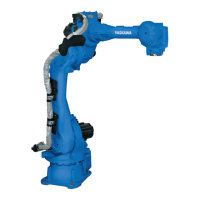
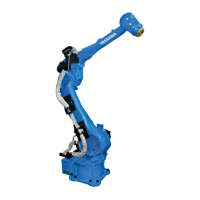
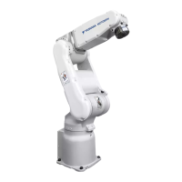
Identifies robot parts and labels for each work axis using diagrams.
Provides detailed measurements and specifications for the robot base mounting.
Illustrates the robot's physical dimensions and defined working envelope.
Details stopping angles and times for emergency stop categories 0 and 1 under various conditions.
Details the dimensions and mounting requirements for the robot's wrist flange.
Specifies maximum allowable loads, torque, and moments for the S-axis and wrist axes.
Shows mounting points and considerations for peripheral equipment and maximum load capacity.
Explains the use of internal cables (3BC, 4BC) and air hoses for peripheral devices.
Details the pin assignments for internal user I/O wiring harnesses and air lines.
Provides detailed wiring diagrams (a and b) illustrating internal connections within the robot system.
Outlines the recommended inspection schedule, methods, and intervals for various robot components.
Provides detailed steps and precautions for changing the robot's battery unit and connecting the pack.
Instructions for refilling or replacing grease in the robot's main and wrist axes, including amounts and procedures.
Guides on calibrating home position, registering axes, changing absolute data, and setting second home positions.
Provides a comprehensive list of recommended spare parts, types, and material numbers for the robot.
Detailed breakdown of components, DWG numbers, and quantities for the S-axis drive assembly.
Lists parts, DWG numbers, and quantities for the L- and U-axis drive assemblies.
Provides a detailed list of parts, DWG numbers, and quantities for the R-axis unit.
Lists components, DWG numbers, and quantities for the robot's wrist unit assembly.
| Model | MH5S II |
|---|---|
| Type | Industrial Robot |
| Manufacturer | YASKAWA |
| Number of Axes | 6 |
| Payload Capacity | 5 kg |
| Repeatability | ±0.02 mm |
| Mounting | Floor, ceiling, wall |
| Power Supply | 200-230V AC, 50/60Hz |
| Controller | YRC1000micro |