Do you have a question about the YASKAWA MPL300-J00 and is the answer not in the manual?
Provides critical safety instructions, including DANGER, WARNING, and CAUTION notices.
Defines key terms and abbreviations used throughout the manual for Yaskawa robots and systems.
Identifies the intended audience and required knowledge for users of this manual.
Outlines the typical applications and purposes for which the robot system is designed.
Details impermissible uses and modifications that can lead to warranty loss and safety hazards.
Describes the manual's content, purpose, and recommendations for effective use.
Covers essential safety information, including emergency stop button functionality and warnings.
Explains the warning message for cooling fan errors and its implications for robot components.
Provides the official address and contact information for Yaskawa Electric Corporation.
Lists the contact details for the authorized representative, YASKAWA Europe GmbH.
Details the standard items included in the robot system delivery package.
Instructs users to verify serial numbers on the robot, controller, and pendant against the type plate.
Outlines precautions and methods for safely transporting the robot system.
Provides guidance on using a crane for robot transportation, including lifting methods.
Details the procedure for transporting the robot using a forklift, including pallet requirements.
Explains the role of shipping brackets and bolts for securing the robot during transport and their removal.
Details essential protective measures and operator responsibilities for safe robot operation.
Specifies required environmental conditions and location criteria for robot installation.
Illustrates a practical example of mounting the robot base plate and fixing the robot to it.
Covers electrical installation standards and regulations for proper grounding of the robot system.
Describes the types of cables and general procedures for connecting the robot system components.
Provides step-by-step instructions for connecting the encoder and power cables to the robot.
Details the procedure for connecting the robot cables to the robot controller unit.
Explains how to connect the programming pendant cable to the designated port.
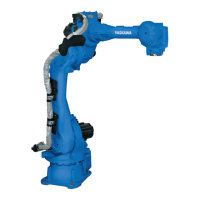
Specifies the robot model type, mounting, degree of freedom, and carrying capacity.
Provides the dimensional specifications for the robot base, including mounting hole details.
Illustrates robot dimensions and outlines the defined operational working area.
Details the adjustable working range for the S-axis and how to modify it.
Lists the components required for adjusting the working area of the S-axis.
Guides the installation of mechanical limits for axes to define operational boundaries.
Explains how to adjust pulse limits for the S-axis to change movement ranges.
Defines coastdown times and distances for safety distance determination during emergency stops.
Presents data on overrun distances and times for Stop category 0 at various deflection levels.
Details stopping angles and times for the S-axis under Stop category 0 conditions.
Details stopping angles and times for the L-axis under Stop category 0 conditions.
Details stopping angles and times for the U-axis under Stop category 0 conditions.
Presents data on overrun distances and times for Stop category 1 at various deflection levels.
Details stopping angles and times for the S-axis under Stop category 1 conditions.
Details stopping angles and times for the L-axis under Stop category 1 conditions.
Details stopping angles and times for the U-axis under Stop category 1 conditions.
Provides dimensions and mounting details for the wrist flange, including threaded holes and PCD.
Discusses mounting options and load considerations for peripheral devices on the S-axis.
Emphasizes that S-axis load must not exceed the robot's permissible bearing capacity for optimal performance.
Presents graphical data and conditions for attaching peripheral equipment and observing moment ratings.
Illustrates the routing and pin assignment for internal cables and pneumatic lines.
Details the process of connecting field bus cables and routing them through the robot's S-head.
Provides a detailed view of the connector used for internal cables, indicating used and unused pins.
Explains requirements for laying internal cables and pneumatic lines through hollow parts, including protection.
Shows the internal wiring diagram for connections between the robot controller and various axes.
Presents the second part of the internal connection diagram for robot axes and components.
Classifies inspections into time levels and outlines checks for daily, 1000, 5000, 9000, 18000, 36000 hour intervals.
Provides information and warnings regarding the battery unit and its replacement.
Step-by-step instructions for safely removing and replacing the battery unit.
Illustrates battery unit connector diagrams for different axes and includes a warning note.
Details safety precautions and procedures for refilling grease in robot components.
Specifies amounts and procedures for replenishing or exchanging grease in the S, L, and U axis gears.
Provides information on grease filling for BT-axis gear and U-axis cross roller bearing.
Lists the specific amounts of grease required for various joints of the robot.
Explains the necessity and general procedures for calibrating the robot's home position.
Provides a detailed step-by-step guide for registering the home position for all robot axes simultaneously.
Details the procedure for registering the home position for each robot axis individually.
Guides users on how to modify the absolute encoder data after setting the home position.
Explains the process of deleting absolute encoder data for robot axes.
Explains the purpose and initial steps for setting a second home position as a check point.
Provides detailed steps for setting the second home position, including moving the robot and modifying data.
Outlines steps to take after an alarm, particularly regarding home position confirmation and PG system checks.
Presents a comprehensive list of recommended spare parts, including category, description, and material numbers.
Provides an exploded view and part number list for the S-axis drive assembly.
Displays exploded views and part numbers for the L-axis drive assembly, parts 1 and 2.
Shows exploded views and a list of parts for the U-axis drive.
Illustrates the components of the wrist unit with corresponding part numbers.
Presents an exploded view and list of parts for the balancer unit.
| Model | MPL300-J00 |
|---|---|
| Manufacturer | YASKAWA |
| Payload Capacity | 300 kg |
| Degrees of Freedom | 6 |
| Number of Axes | 6 |
| Protection Class | IP67 |
| Type | Articulated Robot |
| Mounting | Floor, Wall |