Internal cables and compressed air lines
8 - 43
8 Internal cables and compressed air lines
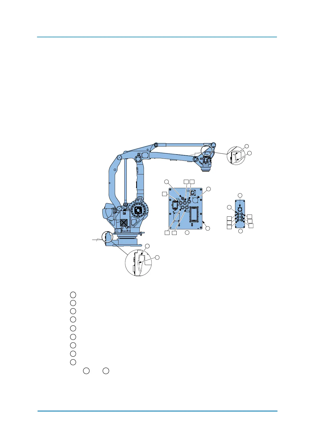
Internal cables 23 wires 23 x 0.50 mm² and 5 pneumatic lines) and air hoses are used in
order to use peripheral devices (e.g. gripper). They are mounted on the upper arm as
shown in the following diagram "Connector for internal cables and compressed air lines".
The pins 1 to 23 are assigned as shown in the following figure. Wiring must be performed
by the user.
The following requirements must be met:
• The total current value for the internal wiring harness must be 44 A .
• The current-carrying capacity per single conductor (cross-section 0.50 mm²) must not
exceed 2 A or less .
• The air pressure for the air hose must not exceed 600 kPA (the inner diameter of the air
hose is Ø 7.5).
Fig. 8-1: Plug for internal cables and compressed-air routing
Air inlet A, B, C, D and E with cap
Connector for the internal cable bushing on the stand
Power input module
View A
There is a connecting plug for internal cable ducting in the case.
Air inlet A, B, C, D and E with cap
Tube for fieldbus cable (Ø12) on casing
View B
Tube for fieldbus cable (Ø12) on stand
and cable
12
1. The robot has included an integrated tube at his disposal for a field bus cable. Already, a cable with a cross-
section of 2 mm² exists in the tube. In order to lead a field bus cable through the robot, you take away the cover
at the terminal strip and the distribution box, you fortify the field bus cable with cable A, and then pull the cable B
on the wrist.
B
A
F
C
B
A
E
D
4
B
A
8
2
3
5
E
D
C
B
S1
2BC
1BC
FB
C
D
E
AB
A
1
6
9
7
1
2
3
4
5
6
7
8
9
A
B
 Loading...