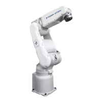
Do you have a question about the YASKAWA MA2010 and is the answer not in the manual?
Key safety warnings, including DANGER, WARNING, and CAUTION levels.
Glossary of common terms used in the manual and their definitions.
Specifies required user knowledge and typical applications for the robot.
Lists prohibited actions and conditions that constitute misuse of the robot system.
Outlines the manual's purpose, scope, and important notes for users.
Details critical safety information, including programming pendant and emergency stop functions.
Provides contact details for the manufacturer and authorized regional representatives.
Lists and illustrates the standard items included with the robot system.
Instructions on verifying serial numbers on the robot, controller, and pendant.
General guidelines and safety warnings for transporting the robot system.
Specific instructions and diagrams for safely transporting the robot using a crane.
Specific instructions and diagrams for safely transporting the robot using a forklift.
Details on shipping brackets, bolts, and rubber buffers used for securing the robot.
Essential safety measures and requirements for installing protective devices around the robot.
Step-by-step guide and diagrams for physically mounting the robot base onto a floor plate.
Illustrates and describes various mounting positions for the robot, including suspended types.
Critical instructions and safety notes regarding proper grounding of the robot system.
Overview and diagrams of the encoder and power cables used to connect the robot.
Step-by-step guide for connecting encoder and power cables to the robot's connector plate.
Instructions for connecting the robot's encoder and power cables to the main robot controller.
Procedure for connecting the programming pendant cable to the robot controller.
Details robot type, mounting, capacity, repeatability, weight, and power consumption.
Specifies the operational movement limits for each of the robot's axes.
Outlines maximum operational speeds, admissible moments, and permissible moments of inertia.
Information on the robot's IP protection ratings and sound pressure level.
Shows robot base dimensions and overall working envelope.
Explains how the S-axis working range can be configured or modified.
Defines overrun distance and time, and factors affecting safety distance calculation.
Graphs detailing stop position and overrun time for Stop Category 0 under various loads.
Details stop position and overrun time for Stop Category 1, independent of load.
Details dimensions, mounting, and preparation for the robot's wrist flange.
Covers maximum load limits for the S-axis and optimal performance considerations.
Specifies allowable wrist load, moments, and inertia, with supporting diagrams.
Details maximum permissible load for U-axis and S-axis, including inertia limits.
Illustrates and describes methods for mounting peripheral equipment onto the robot's arms.
Details internal cable types, wire counts, cross-sections, and air hose pressure requirements.
Identifies various connector types and provides diagrams for internal wiring and air lines.
Specifics on welding power cable integration and details of connector plugs and pin assignments.
Detailed electrical schematics showing internal connections for various robot axes and components.
Critical safety warnings and notices regarding maintenance procedures and data loss.
Introduces the inspection schedule, its purpose, and classifications based on staff and intervals.
Provides instructions and diagrams for changing the robot's battery unit to prevent data loss.
General guidelines and precautions to follow when performing grease replenishment on robot gears.
Covers home position calibration, registering axes, changing data, and clearing absolute data.
Details setting the second home position and procedures after specific alarms.
Categorizes spare parts (A, B, C) and provides a list of recommended items for stocking.
Illustrates and lists all parts associated with the S-axis unit of the robot.
Illustrates and lists all parts associated with the L-axis unit of the robot.
Illustrates and lists all parts associated with the U-axis drive of the robot.
Illustrates and lists all parts associated with the R-axis unit of the robot.
Illustrates and lists all parts associated with the robot's wrist unit.
Illustrates and lists all parts associated with the robot's gear units.
