EasyManuals Logo

YASKAWA MA2010 User Manual

YASKAWA MA2010
94 pages
To Next Page IconTo Next Page
To Previous Page IconTo Previous Page
Page #39 background imageLoading...
Page #39 background image
Allowable load for wrist axis and wrist flange
7
- 39
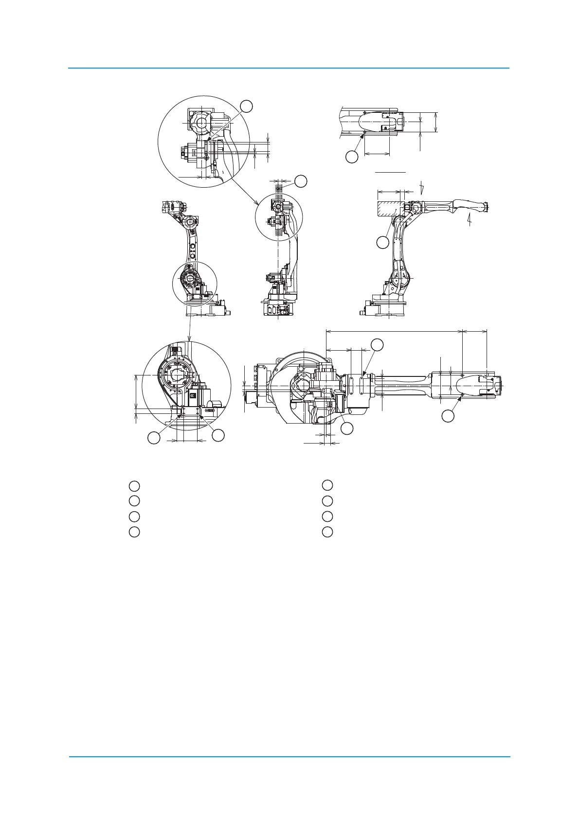
Fig. 7-3: Installing peripheral equipment mounts
4 threaded holes M8 x 16 4 threaded holes M6 x 12
2 threaded holes M6 x 12 4 threaded holes M6 x 14
Mount the peripherals in this range. 2 threaded holes M10 x 12
Mount the accessories, so that the
centre of gravity of the accessories is
in the U arm within this range.
2 threaded holes M10 x 18
All dimensions in mm
165
70
130
70
130
165
15
48
15
6
28.5
13 26
45
15
100
168
70
917
300
60
45
92
30 229
50
B
A
1
2
3
4
5
2
6
7
8
View B
1
5
2
6
3
7
4
8

Table of Contents

Questions and Answers:

Question and Answer IconNeed help?

Do you have a question about the YASKAWA MA2010 and is the answer not in the manual?

YASKAWA MA2010 Specifications

General IconGeneral
BrandYASKAWA
ModelMA2010
CategoryRobotics
LanguageEnglish

Related product manuals