Internal cables and compressed air lines
8
- 42
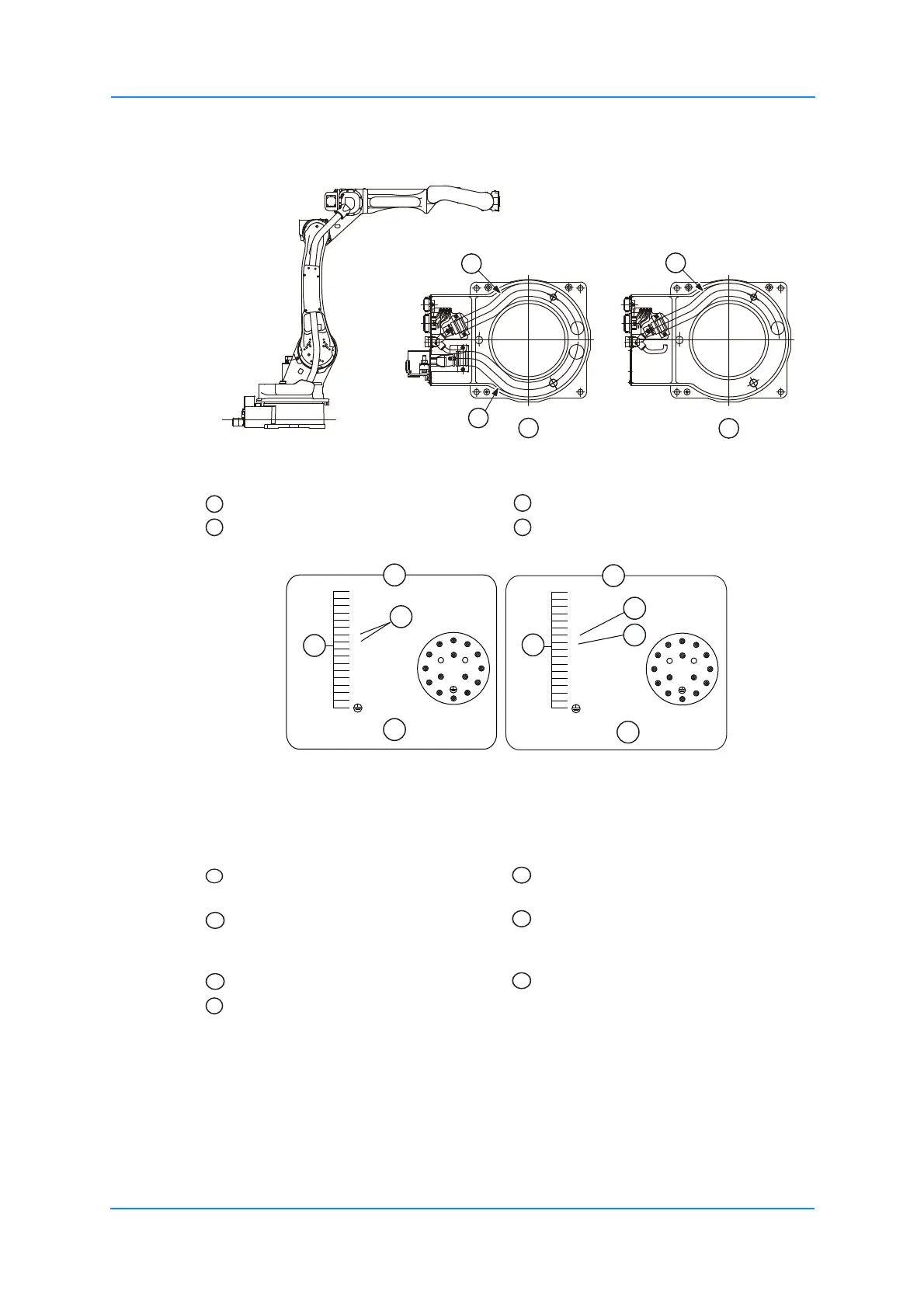
The welding power cable is only integrated as standard in the robot MA2010-A00. Fig. 8-2:
"Robot type Welding power cable").
Fig. 8-2: Robot type Welding power cable
Fig. 8-3: Details of the plug
The pins used on the connectors (3BC: 14 wires 8 x 0.20 mm², 2 x 0.75mm² and 4 x 1.25
mm²) are connected to the stand and arm with individual wires.
In the standard specification, pins 7 and 8 are connected as follows:
• To the 3BC connection for the collision sensor on the U arm.
• To the 3BC connection for the collision sensor on the robot controller.
Pins 7 and 8 of the respective 3BC connections on the connector plate and U arm are
connected to each other.
Internal wiring harness Section A-A MA2010-A00
Welding power cable Section -A MA2010 A10
= assigned
= unassigned
Connector plug for the internal cable
feedthrough on the connector base
Pins used
Connector plug for the internal cable
feedthrough on U-arm
Internal user I/O wiring harness: 8
wires 0.2 mm², 2 wires 0.75 mm², 4
wires 1.25 mm²
+24 V (1A) for shock sensor 7 and 8 are open
Shock sensor signal input
1
6
10
14
8
12
7
11
5
16
15
4
9
13
2
3
3
4
5
1
2
9
10
11
16
15
13
14
12
6
(0.75mm
2
)
(0.75mm
2
)
7
8
(1.25mm
2
)
(1.25mm
2
)
(1.25mm
2
)
(1.25mm
2
)
1
6
10
14
8
12
7
11
5
16
15
4
9
13
2
3
3
4
5
1
2
9
10
11
16
15
13
14
12
6
7
8
(0.75mm
2
)
(0.75mm
2
)
(1.25mm
2
)
(1.25mm
2
)
(1.25mm
2
)
(1.25mm
2
)
1
2
3
4
5
5
6
6
7
1
2
3
4