www.dadehpardazan.ir 88594014-15
System Startup and Setup
4.1.5
I/O Allocations
4-6
4
4.1.5 I/O Allocations
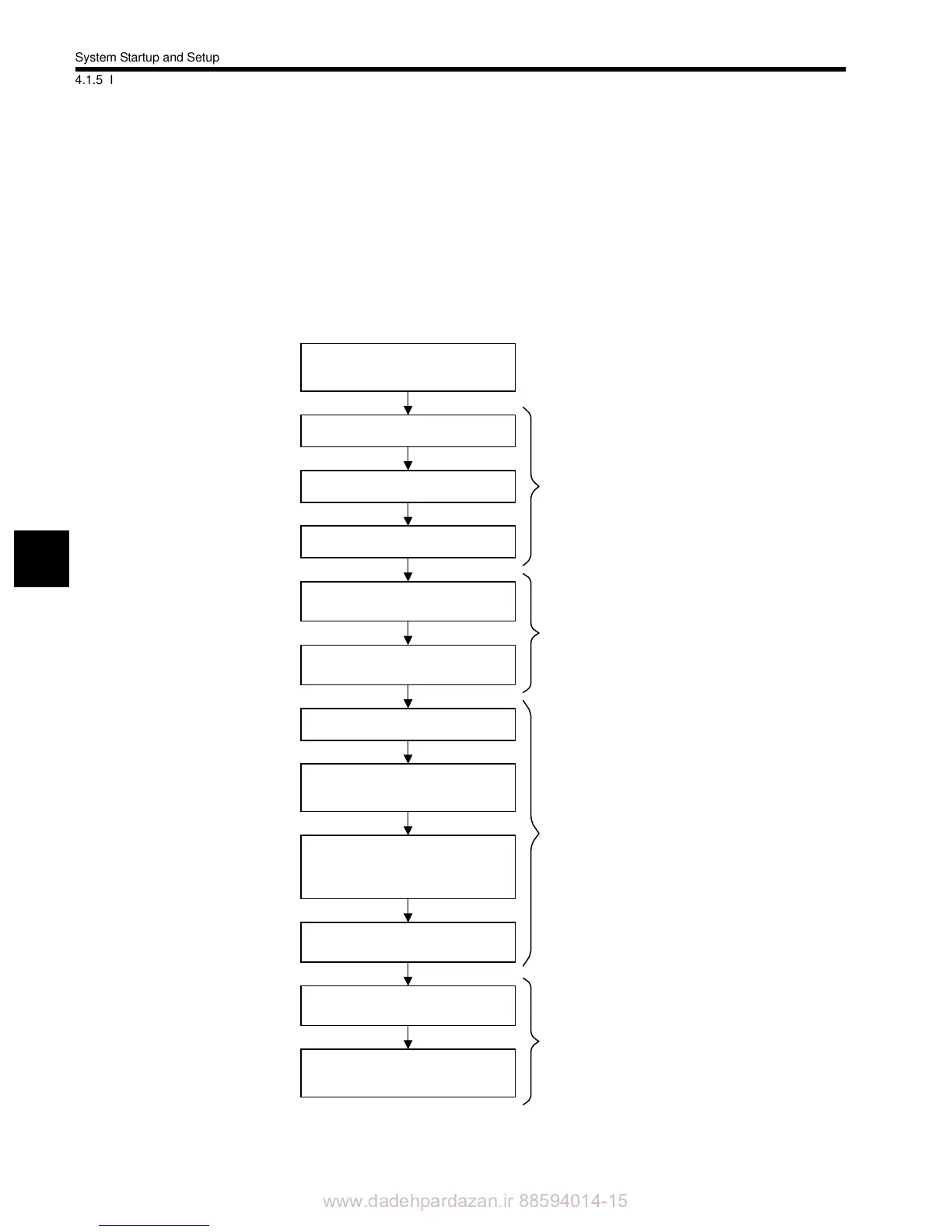
After selecting the device and wiring the cables, allocate I/O to start 260IF Module commu-
nications.
The following flowchart shows the basic setting procedure using the CP-717 online func-
tions.
For details on basic CP-717 operation, refer to MP900 Series Machine Controller User's
Manual: Programming Panel Software (Manual No.: SIEZ-C887-2.3, 2.4, to be prepared).
Connect the Programming Device
(CP-717 Engineering Tool) and the
MP920/MP940D with a communica-
Turn ON the communications power
supply.
Turn ON the Slave power supply.
The different power supplies can
be turned ON simultaneously.
Turn ON the MP920/MP940D power
supply.
Start the Programming Device
(CP-717).
In online mode, log on to the MP920/
MP940D.
Display the Module Configuration
Window.
Set “260IF” for the slot to which the
260IF Module is mounted.
Open the 216IF Definitions Window
and allocate the node addresses and
I/O registers for the connected
devices.
Close the Module Configuration
Window.
Check that the MS and NS indica-
tors on the 260IF Module are lit
Check that the MS and NS indica-
tors on the connected Slaves are lit
(green).
Refer to
Machine Controller
MP900 Series Machine Controller
User's Manual: Programming
Panel Software
(Manual No.:
SIEZ-C887-2.3, 2.4, to be pre-
pared).
Refer to
4.3 260IF Module Setup and
MP900 Series Machine Controller
User's Manual: Programming Panel
Software
(Manual No.: SIEZ-C887-2.3,
2.4, to be prepared).
If the MS and NS indicators are
lit red or are flashing red, refer to
6.4 Troubleshooting.
 Loading...


