www.dadehpardazan.ir 88594014-15
System Startup and Setup
4.3.1
Opening the 260IF Module Configuration Window
4-10
4
4.3 260IF Module Setup
The 260IF Module is set up from the CP-717 Engineering Tool.
4.3.1 Opening the 260IF Module Configuration Window
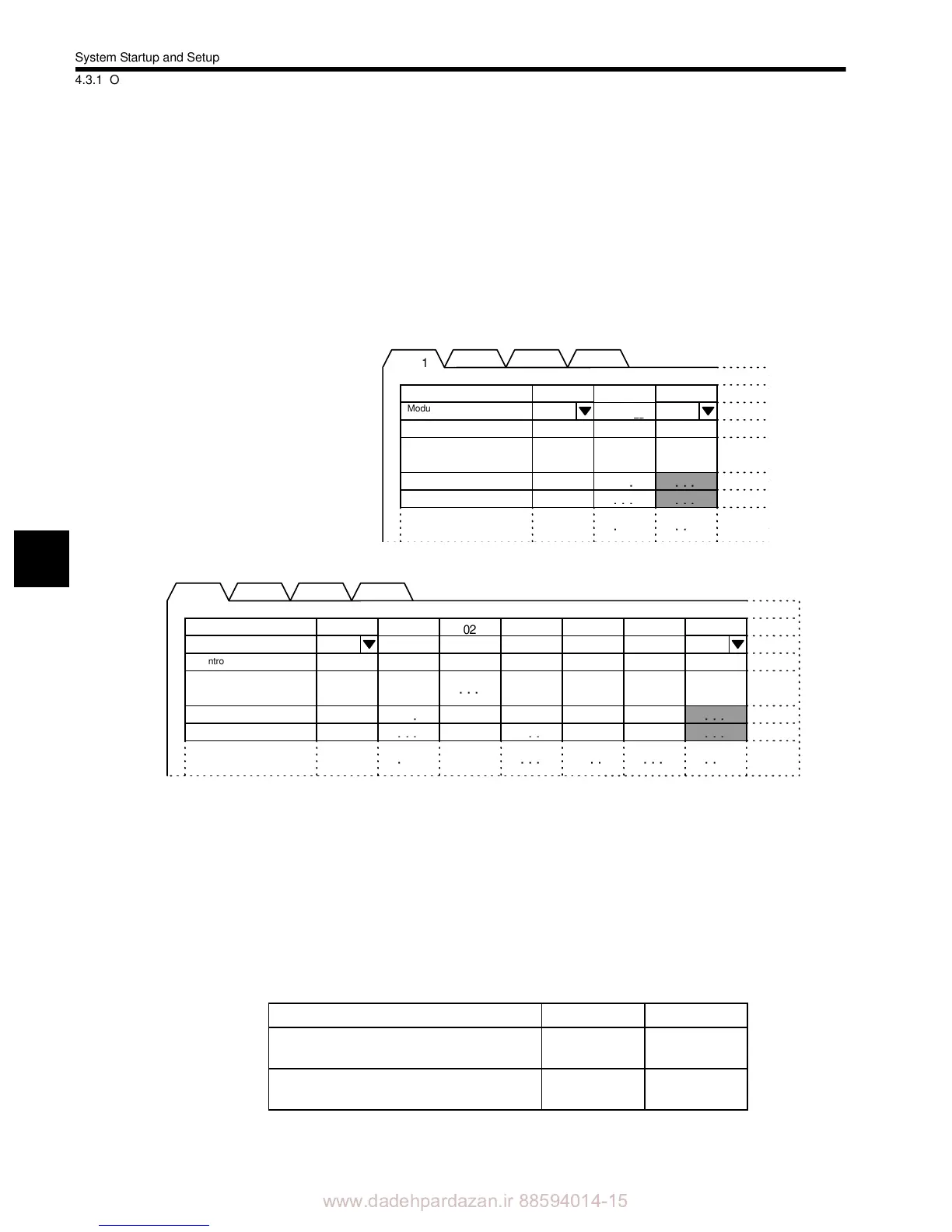
1. Double-click the Module Configuration Definition Box for the Controller mounted to
the 260IF Module to display the Module Configuration Window.
Fig 4.4 MP920 Module Configuration Window
Fig 4.5 MP940 Module Configuration Window
For the MP920, set the 260IF Module for the slot in which the 260IF Module is
mounted. In the above example showing the MP920 Module Configuration Window, the
260IF Module is set in slot 02.
For the MP940, the 260IF Module is always in slot 06, but 260IF Module must still be
set.
The leading and end I/O register numbers must be set for the 260IF Module. Allocate I/
O registers within the ranges shown in the following table.
2. Double-click the slot where the 260IF Module is set and open the 260IF Definition Win-
dow.
Rack 1
Module
Controller CPU No.
I/O Start register
I/O End register
No
MP920 RESERVED SERIAL LIO SVA CNTR 260IF
MP920 MP940D
Leading I/O register
(Offset of leading IW/OW register)
0000 to 13FF 0000 to 07FF
End I/O register
(Offset of end IW/OW register)
0000 to 13FF 0000 to 07FF
 Loading...


