u
Main Circuit Connection Diagram
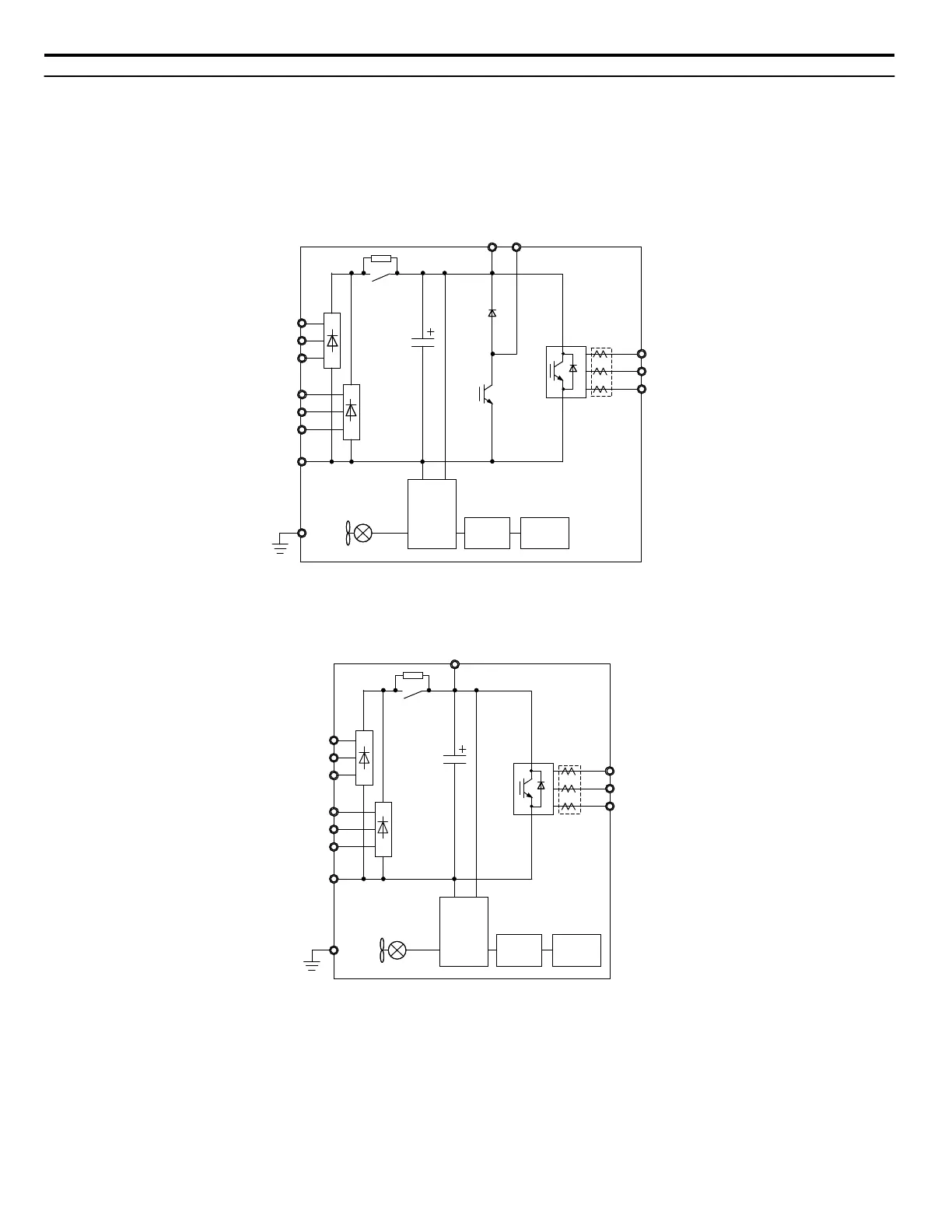
Refer to Figure 5, Figure 6, and Figure 7 when wiring the main circuit of the drive. Connections may vary based on drive
capacity.
NOTICE: Do not use the negative DC bus terminal “
⊖
” as a ground terminal. This terminal is at high DC voltage potential. Improper wiring
connections could damage the drive.
n
6-Phase/12-Pulse Input 400 V Class Models 4T0058o and 4T0072o
R1/L11
S1/L21
T1/L31
Gate
Board
Control
Board
Operator
B1
R/L1
S/L2
T/L3
–
U/T1
V/T2
W/T3
Relay
Current
Sensor
B2
Figure 5 Connecting Main Circuit Terminals
n
6-Phase/12-Pulse Input 400 V Class Models 4T0088o to 4T0139o
Gate
Board
Control
Board
Operator
+3
R/L1
S/L2
T/L3
R1/L11
S1/L21
T1/L31
–
U/T1
V/T2
W/T3
Relay
Current
Sensor
Figure 6 Connecting Main Circuit Terminals
3 Electrical Installation
20
YASKAWA TOEP YAIP1U 04A YASKAWA AC Drive – P1000 6-Phase/12-Pulse Input Installation Manual

 Loading...


