5 Installation Procedure
YASKAWA ELECTRIC TOBP C730600 75B YASKAWA AC Drive Option PG-B3 Installation Manual 27
5.
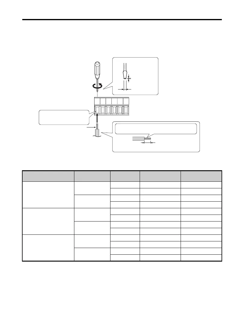
Wire the motor PG encoder to the terminal block on the option according to
Figure 17.
Refer to Figure 21 for the PG-B3 Option and PG Encoder connection diagram.
Refer to Table 9 for a detailed description of the option terminal functions.
Figure 17
Figure 17 Connect Cable Wiring
Table 4 Parameter Settings and Connections for Different Encoder Types
PG Encoder type Control Method
Number of PG
Encoders
F1-21 Setting F1-37 Setting
Single-Pulse (A)
V/f w/PG
10 N/A
2N/A 0
CLV
1N/A N/A
2N/A N/A
Two-Pulse (AB Quadrature)
V/f w/PG
11 N/A
2N/A 1
CLV
1 None Required None Required
2 None Required None Required
Two-Pulse with Z Marker
V/f w/PG
11 N/A
2N/A 1
CLV
1 None Required None Required
2 None Required None Required
Option terminal block
Screwdriver blade size
about 5.5 mm (7/32”)
When not using crimped
insulated sleeves
Pull back the shielding and lightly twist the end
with fingers, keeping the ends from fraying.
Wire crimping ferrule terminals
or not soldered ends
Loosen the screws and
insert the wire into the
opening on the terminal block.
Blade depth of
0.4 mm or less
Blade width of
2.5 mm or less
TOBP_C730600_75B_1_0_E.book 27 ページ 2017年2月17日 金曜日 午後3時2分