15IM 04P02B01-02E
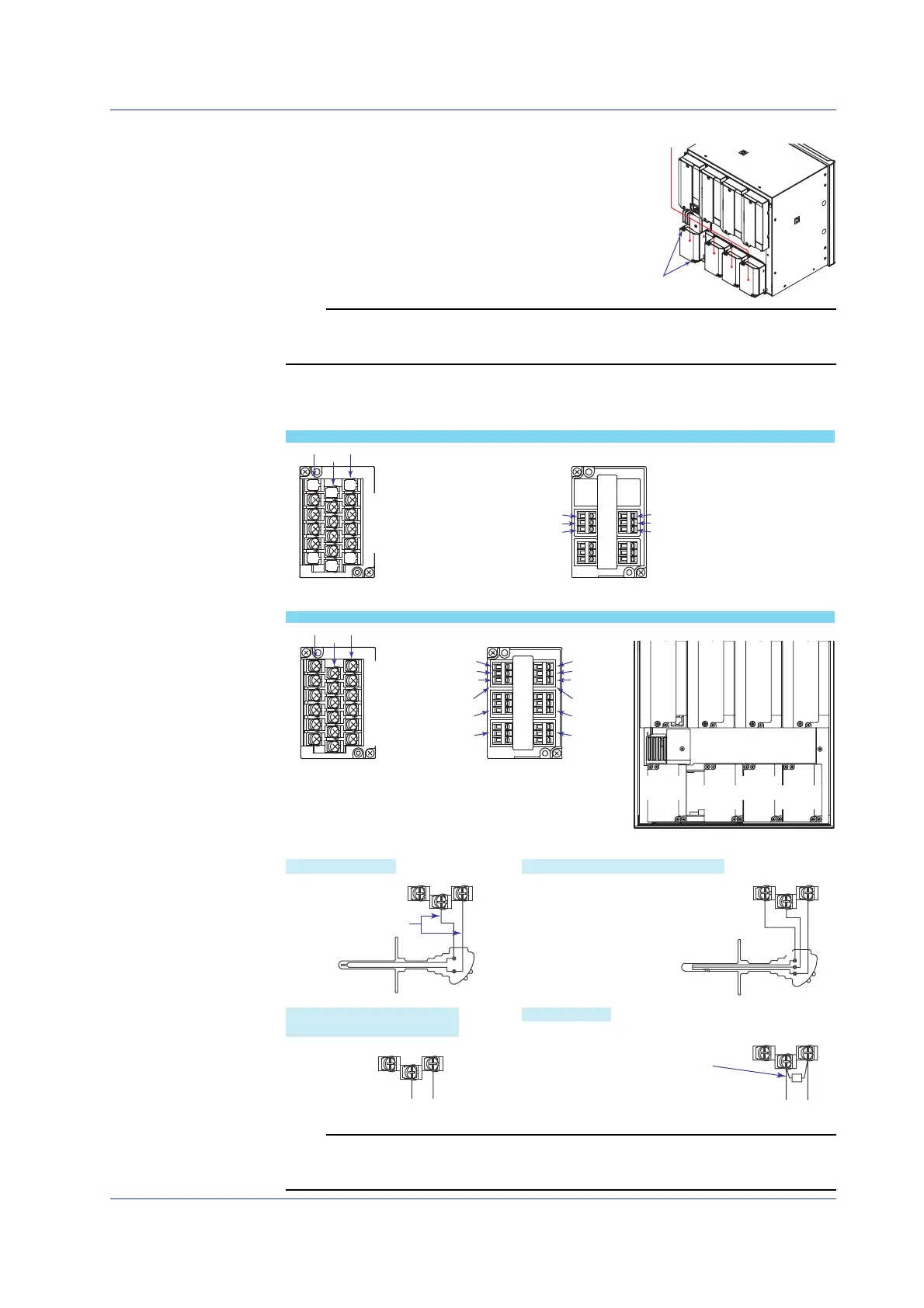
Wiring Procedure
A terminal cover is screwed in place on the
measuring input terminal block on the rear panel.
A label indicating the terminal arrangement is
affixed to the cover.
1.
Turn OFF the recorder and remove the
terminal cover.
2.
Connect the signal wires to the terminals.
Note
Input signal wires of diameter less than or equal to 0.3 mm may not be secured firmly for
clamped terminals (/H2). Fold over the conducting section of the wire, for example, to make
sure that the wire is securely connected to the clamped terminal.
3.
Replace the terminal cover and fasten it with screws.
The proper torque for tightening the screws is 0.6 N-m.
+/A
–/B
b
Channel 1
Channel 3
Channel 5
Channel 2
Channel 4
Channel 6
+A
–/B
b
+A
–/B
b
Screw input terminal Clamped input terminal
(/H2 option)
+/A
–/B
b
+/A
–/B
b
Channel 1
Channel 3
Channel 2
Channel 4
+/A
–/B
b
Screw input terminal Clamped input terminal
(/H2 option)
Pen Model
Dot Model
Channel
1 to 6
Channel
7 to 12
Channel
13 to 18
Channel
19 to 24
Channel 1
Channel 2
Channel 3
Channel 4
Channel 1
Channel 2
Channel 3
Channel 4
Channel 5
Channel 6
Channel location on the input terminals
Measuring Input Wiring
––
DC voltage, 1-5V, ON/OFF
Extension leadwire
DC current
Shunt resistor
–/Bb +/A
–/Bb +/A
–/Bb +/A
–/Bb +/A
++
Thermocouple input Resistance temperature detector input
DC voltage input, 1-5V input,
and ON/OFF input
DC current input
Leadwire resistance:
10 Ω max./wire. The resistance of the three
wires should be equal.
Example: For a 4 to 20 mA input,
a shunt resistor of 250 Ω ± 0.1%
can be used to convert to 1-5V input.
A
B
b
Note
RTD input terminals A and B on the dot model are isolated on each channel. Terminal b is
shorted internally across all channels. However, for 3 legs isolated RTDs (/N2 option), input b
is also isolated for each channel.
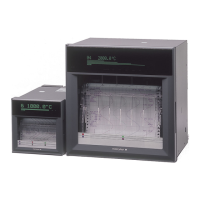
Installing/Wiring the Recorder
Measuring input
terminal block
Terminal cover
attachment screws
 Loading...


