16 IM 04P02B01-02E
Optional Terminal Wiring
WARNING
• To prevent electric shock while wiring, ensure that the power supply source is
turned OFF.
• If a voltage of more than 30 VAC or 60 VDC is to be applied to the output
terminals, use ring-tongue crimp-on lugs with insulation sleeves on all terminals
to prevent the wires from slipping out when the screws become loose.
Furthermore, use double-insulated wires (dielectric strength of 2300 VAC or
more) for the signal wires on which a voltage of more than 30 VAC or 60 VDC is
to be applied. For all other wires, use basic insulated wires (dielectric strength of
1390 VAC). To prevent electric shock, attach the terminal cover after wiring and
make sure not to touch the terminals.
CAUTION
• The option terminals of this instrument are specific to this instrument. Do not
connect the option terminals of the µR1000, µR1800 or other models, as
malfunction may result.
• To prevent fire, use signal wires having a temperature rating of 70°C or more.
• If a strong tension is applied to the cable wired to the recorder, the terminals of
the recorder and/or the cable can be damaged. In order to prevent tension from
being applied directly on the terminals, fasten all wiring cables to the rear of the
mounting panel.
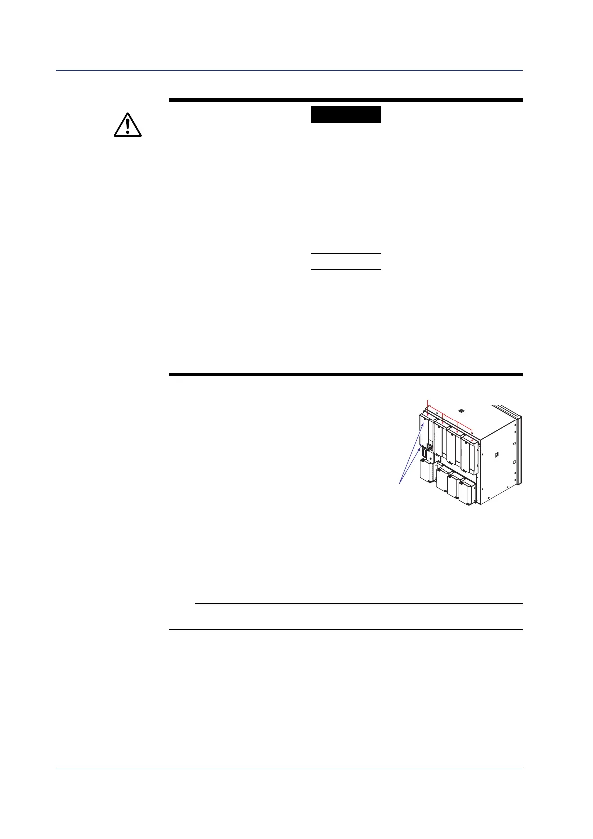
Wiring Procedure
As shown in the figure below, the optional terminal
block is located on the rear panel. The optional
terminal block is provided on the recorder when an
option that requires input/output is installed such as
the alarm output relay (/A1, /A2, /A3, /A4, or /A5
option), FAIL/chart end output (/F1 option), and
remote control function (/R1 option). A terminal
cover is screwed in place on the measuring input
terminal block. A label indicating the terminal
arrangement is affixed to the terminal block.
1.
Turn OFF the recorder and remove the terminal cover.
2.
Connect the input signal wires to the terminals.
3.
Replace the terminal cover and fasten it with screws.
The proper torque for tightening the screws is 0.6 N-m.
Note
To reduce noise, use a shielded cable for the wiring of the remote control input terminals.
Connect the shield to the ground terminal of the recorder.
Installing/Wiring the Recorder
Optional terminal block
Terminal cover
attachment screws
 Loading...


