IM 01E20F02-01E
2-1
2. ABOUT FIELDBUS
2. ABOUT FIELDBUS
2.1 Outline
Fieldbus is a widely used bi-directional digital communi-
cation protocol for field devices that enable the simulta-
neous output to many types of data to the process
control system.
The AXF Series Fieldbus communication type employs
the specification standardized by The Fieldbus Founda-
tion, and provides interoperability between Yokogawa
devices and those produced by other manufacturers.
Fieldbus comes with software consisting of AI, DI, IT,
AR and optional PID function blocks that enable the
flexible implementation of systems.
For information on other features, engineering, design,
construction work, startup and maintenance of
Fieldbus, refer to “Fieldbus Technical Information” (TI
38K03A01-01E).
2.2 Internal Structure of AXF
The AXF contains two Virtual Field Devices (VFD)
that share the following functions.
2.2.1 System/network Management VFD
• Sets node addresses and Physical Device tags (PD
Tag) necessary for communication.
• Controls the execution of function blocks.
• Manages operation parameters and communication
resources (Virtual Communication Relationship:
VCR).
2.2.2 Function Block VFD
(1)Resource block
• Manages the status of AXF hardware.
• Automatically informs the host of any detected
faults or other problems.
(2)Transducer block
• Converts the flow sensor output to the volumetric
flow rate signal, and transfers to the AI function
block.
• Transfers limit switch signals to DI function blocks.
• Adhesion diagnosis levels are set and monitored.
(3)AI function blocks
•Condition raw data from the transducer block,
including scaling and damping (with a first-order
lag), and allow input simulation.
• Outputs volumetric or mass flow rate signals.
(4)DI function blocks (two)
• Limit switches for the flow rate and adhesion alarm,
warning.
(5)IT function blocks (two)
• Add two main inputs and integrate them for output.
(6)AR function block
• Switches two main inputs of different measurement
ranges and combines the result with three auxiliary
inputs through the selected compensation function to
calculate the output.
(7)PID function block (optional)
• Performs the PID control computation based on the
deviation of the measured value from the setpoint.
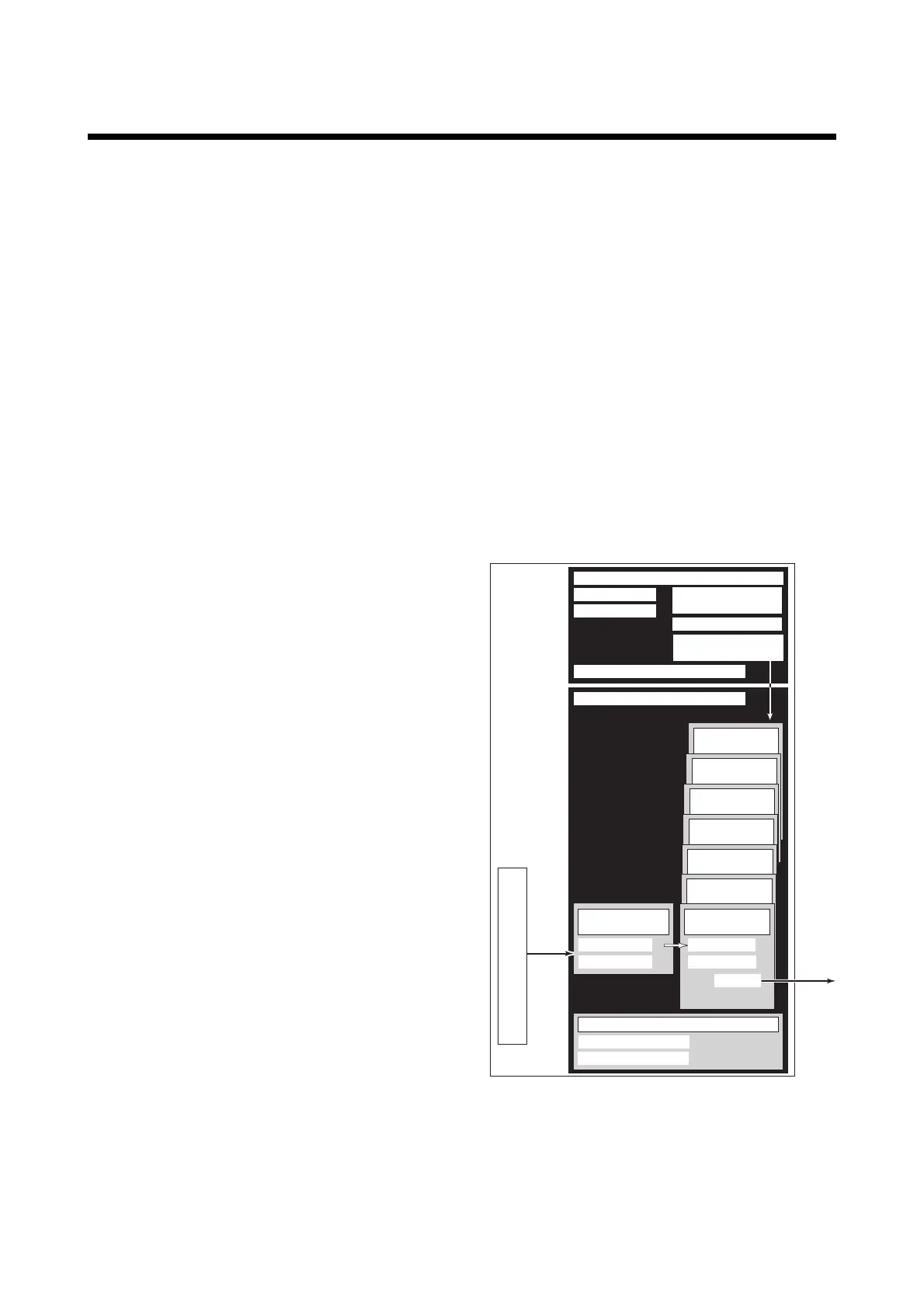
2.3 Logical Structure of Each
Block
PID function
block (option)
F0201.EPS
AXF
Fieldbus
System/network management VFD
Function block VFD
Link Master
PD Tag
Resource block
Block tag
Parameters
Communication
parameters
VCR
Node address
Function block
execution schedule
AR function
block
IT function
block
IT function
block
AI function
block
DI function
block
Sensor
input
Output
SENSOR
Transducer block
Block tag
Parameters
DI function
block
Block tag
OUT_D
Parameters
Sensor
Figure 2.1 Logical Structure of Each Block
Setting of various parameters, node addresses, and PD
Tags shown in Figure 2.1 is required before starting
operation.

 Loading...


