Figure 6.3.3 Removing the Front Cover and Mounting
Screws of Display Unit for AXFA11 Remote
Converter
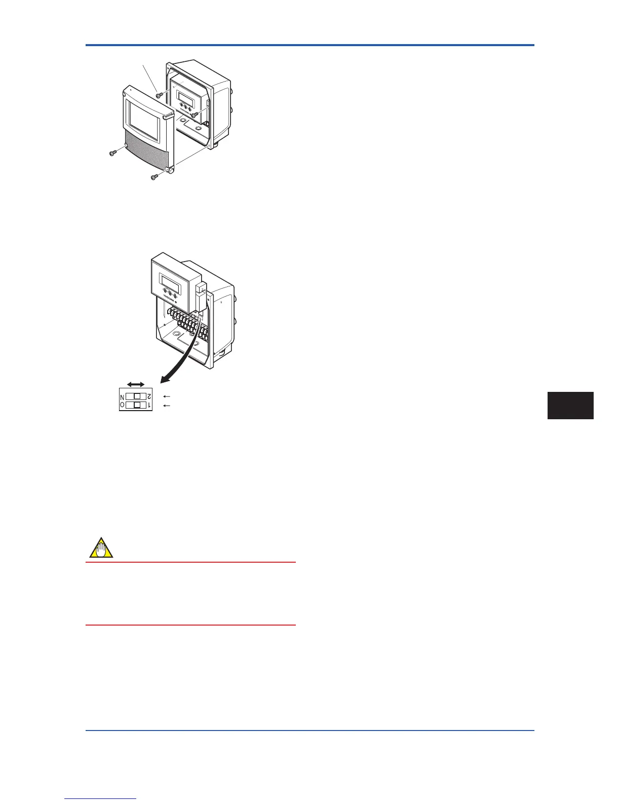
(4) Lift the display unit (See Figure 6.3.4).
At this time, do not remove the connector.
Low High
Figure6.3.4 SwitchCongurationforAXFA11Remote
Converter
(5) Set the switches. There are two switches (See Figure
6.3.4). One is for burnout setting and the other for
write protect setting, located adjacent to each other.
(6) Taking care not to entangle the cables, install the
display unit with two mounting screws.
(7) Install the cover.
NOTE
Ontheamplier’sCPUboard,theburnoutsetting
switch (i.e., Switch 1) and the write protect switch
(i.e., Switch 2) are located adjacent to each other.
Accordingly, special care should be taken when
making switch settings.
 Loading...

