10. Explosion Protected Type Instrument
In this chapter, further requirements and differences for
explosion proof type instrument are described.
NOTE
When describing the model name like AXFC in
thismanual,“”meansanyofthefollowing.
002, 005, 010, 015, 025, 032, 040, 050, 065, 080, 100,
125, 150, 200, 250, 300, 350, 400
WARNING
Magneticowmeterswiththemodelname
AXFCmagneticowmeterandAXFA14C
remote converter are products which have been
certiedasexplosionprooftypeinstruments.Strict
limitations are applied to the structures, installation
locations, external wiring work, maintenance and
repairs,etc.oftheseinstruments.Sufcientcaremust
be taken, as any violation of the limitations may cause
dangerous situations.
Be sure to read this chapter before handling the
instruments.
For explosion proof type instrument, the description in
this chapter is prior to other description in this user’s
manual.
For ATEX or IECEx explosion proof type, be sure to
read IM 01E20A01-11EN.
For TIIS explosion proof type, be sure to read
“INSTALLATIONANDOPERATINGPRECAUTIONS
FORTIISFLAMEPROOFEQUIPMENT”attheendof
this manual.
WARNING
The terminal box cover and display cover is locked by
special screw. In case of opening the cover, use the
hexagonal wrench attached.
The covers of explosion proof type products are
locked. Use the attached hexagonal wrench to open
and close the cover. Before opening the cover, be sure
tocheckthatthepowerofowmeterhasbeenturned
off. Once the cover is closed, be sure to re-lock the
product.
Be sure to lock the cover with the special screw using
the hexagonal wrench attached after tightening the
cover.
10.1 ATEX
NOTE
ForATEXexplosionprooftypespecication,referto
IM 01E20A01-11EN.
10.2 FM
(1) Technical Data
(AXF Integral Flowmeter), (AXF Remote Flowtube)
Applicable Standard:
FM3600, FM3610, FM3615,
FM3810, ANSI/NEMA 250
(AXF Integral Flowmeter)
Explosion proof for Class I, Division 1, Groups A, B, C &
D.
Dust-ignition proof for Class II/III, Division1, Groups E, F
& G.
Intrinsically safe (electrodes) for Class I, Division 1,
Groups A, B, C & D.
“SEALALLCONDUITSWITHIN18INCHES”
“WHENINSTALLEDINDIV.2,SEALSNOTREQUIRED”
Electrode Circuit Um: 250 Vac/dc
Maximum power supply voltage: 250 Vac/130 Vdc
Excitation Circuit: 140V max
Enclosure: NEMA 4X
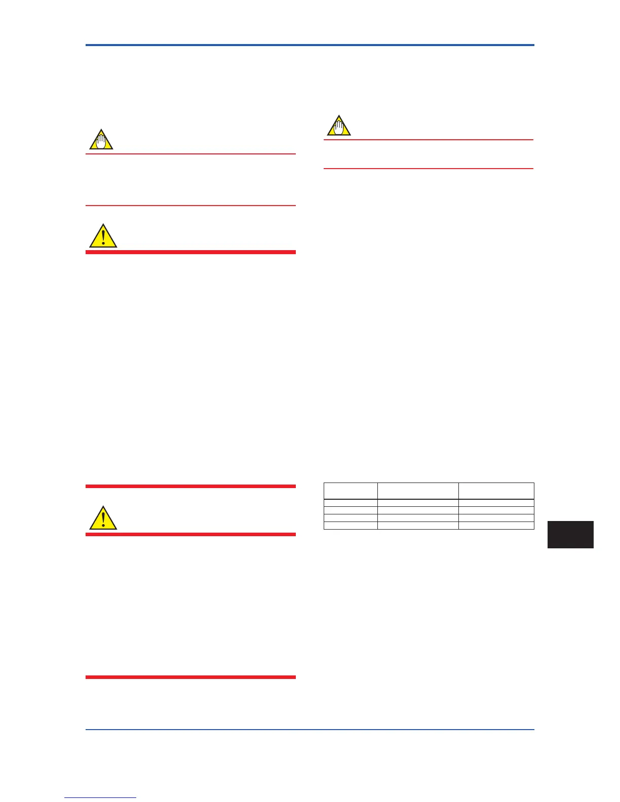
Temperature Code: T6
Note: Temperature Code T5 to T3 included in the scope of
application and its approval
Refer to following table;
Temperature
Code
Maximum Process
Temperature
Minimum Process
Temperature
T6 +70°C (+158F) –40°C (–40°F)
T5 +85°C (+185F) –40°C (–40°F)
T4 +120°C (+248F) –40°C (–40°F)
T3 +130°C (+266F) –40°C (–40°F)
Ambient Temp.: –40°C to +60°C (–40°F to +140°F)
 Loading...

