6.3 Write Protect Switch
Bysettingthewriteprotectfunctionto“Protect”itis
possible to prevent the overwriting of parameters.
Write protection can be carried out using either the
hardware switch on the CPU board (i.e., Switch 2) (See
Figure 6.3.2) or software parameter settings. If either
oftheseitemsissetto“Protect,”theoverwritingof
parameters will be prohibited.
NOTE
• Ifthehardwareswitchissetto“Protect,”itwillnot
be possible to overwrite parameters; furthermore,
this condition will be maintained until the switch is
setto“Enable.”
• Inthecaseofeldbuscommunicationtype,setting
of the hardware switch (Enable or Protect) is
ineffective and write protection can be carried out
only by software parameter settings.
For more details regarding usage of the write protect
function and the software’s parameter switches, refer to
“ParameterDescription”oftheappropriatemanualwhich
can be downloaded from our website.
6.3.1 Setting Hardware Switch of Integral
Magnetic Flowmeter or AXFA14 Re-
mote Converter
IMPORTANT
To preserve the safety, do not touch the electrical
circuit and the cables except the setting switches.
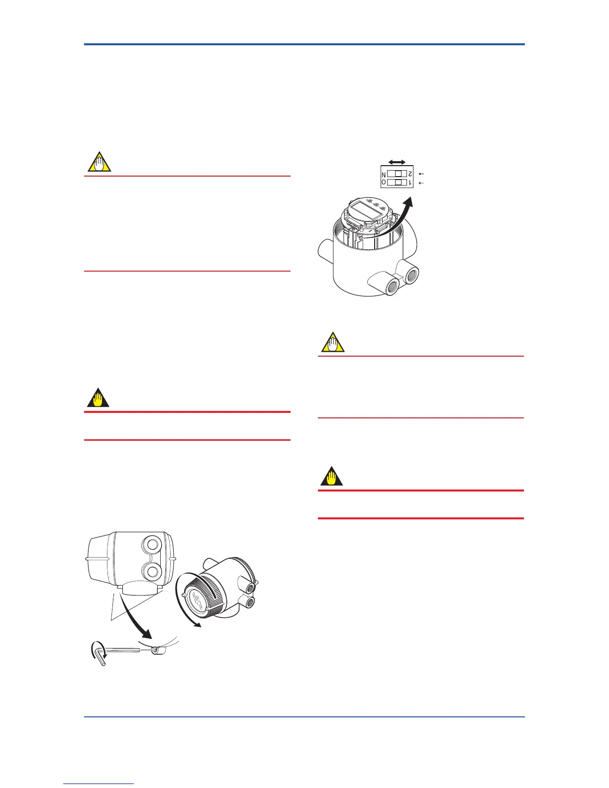
(1) Turn off the power.
(2) Loosen cover locking screw 1 clockwise using a
hexagonal wrench (nominal size 3) to unlock the
cover. (Upon shipment from the manufacturing
plant,thecoverislocked.)Holdtheowmeterwith
your hand and remove the cover by turning it in the
direction of the arrow as shown below.
1 2
Figure 6.3.1 Removing the Display Cover for Integral
Flowmeter and AXFA14 Remote Converter
(3) Set the switches. There are two switches (See Figure
6.3.2). One is for burnout setting and the other for
write protect setting, located adjacent to each other.
(4) Taking care not to entangle the cables, install the
covertotheowmeterbyturningitinthebackward
direction of the arrow as shown Figure 6.3.1.
(5) Tighten cover locking screw 1 counterclockwise
using a hexagonal wrench (nominal size 3) to lock the
cover.
Switch 1
2 Burnout setting switch
1 Write protect setting switch
Figure6.3.2 SwitchCongurationforIntegralFlowmeter
and AXFA14 Remote Converter
NOTE
Ontheamplier’sCPUboard,theburnoutsetting
switch (i.e., Switch 1) and the write protect switch
(i.e., Switch 2) are located adjacent to each other.
Accordingly, special care should be taken when
making switch settings.
6.3.2 Setting Hardware Switch of AXFA11
Remote Converter
IMPORTANT
To preserve the safety, do not touch the electrical
circuit and the cables except the setting switches.
(1) Turn off the power.
(2) While supporting the front of the cover with your hand,
iptheconnectingscrewprotectivecoverover,and
remove the four connecting screws.
(3) Loosentheamplierassembly’stwoscrewswhile
supporting it with your hand (See Figure 6.3.3).
 Loading...

