(4) Maintaining Stable Fluid Conductivity
IMPORTANT
Donotinstalltheowmeterwhereuidconductivity
tends to become uneven. If chemicals are fed near
theupstreamsideofamagneticowmeter,theymay
affecttheowrate’sindications.Toavoidthissituation,
it is recommended that the chemical feed ports be
locatedonthedownstreamsideoftheowmeter.If
it is unavoidable that chemicals must be fed on the
upstreamside,provideasufcientlengthofstraight
run (approximately 50D or more) to ensure the proper
mixtureofuids.
(Correct)
Downstream side
F0302.ai
Figure 3.1.2 Chemical Injection
(5) Precautions for Use of Liquid Sealing
Compounds
IMPORTANT
Care must be taken in using liquid sealing compounds
onthepiping,asitmayhaveanegativeinuence
ontheowindicationsbyowingoutandcovering
the surfaces of an electrode or grounding ring. In
particular, care must be taken if a liquid sealing
compound is used in the case of vertical piping.
(6) Service Area
Select locations where there is adequate space to service
installing, wiring, overhauling, etc.
(7) Bypass Line
It is recommended to install a bypass line to facilitate
maintenance and zero adjustment.
Figure 3.1.3 Bypass Line
(8) Supporting the Flowmeter
CAUTION
Donotsecuretheowmeterseparatelytopreventthe
vibrations, shocks, and expansion and contraction forces
ofthepipingfromaffectingit.Fixthepipesrst,then
supporttheowmeterwiththepipes.Withextrasmall-
sizedowmeters(sizes2.5to10mm(0.1to0.4in.)),in
particular,xtheowmeterinparallelwiththepipingona
mounting base.
(9) Mounting Positions
Pipesmustbefullylledwithliquids.
IMPORTANT
Itisessentialthatpipesremainfullylledatalltimes,
otherwiseowrateindicationsmaybeaffectedand
measurement errors may be caused.
Piping shall be designed so as to maintain the interior
oftheowtubelledwithuids.
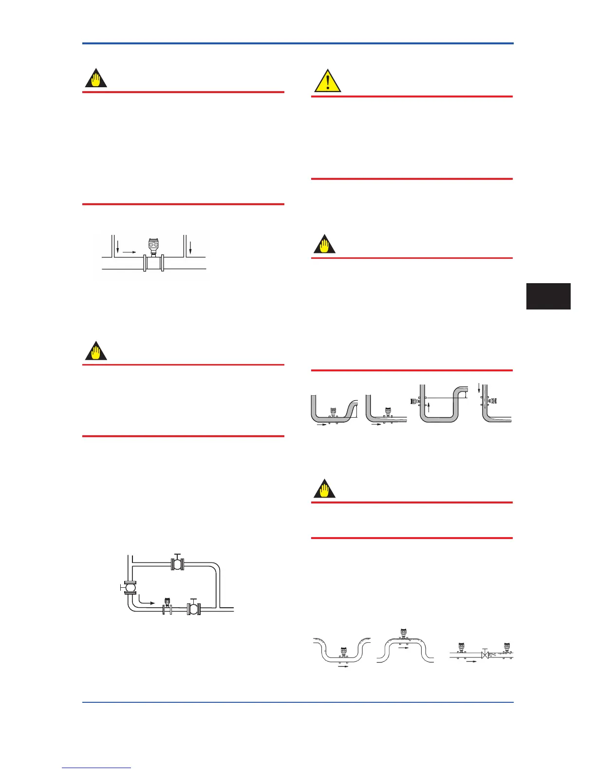
Vertical mounting is effective in such cases as
whenuidstendtoseparateorsolidmattermaybe
precipitated. When employing vertical mounting, direct
theuidsfromthebottomtothetoptoensurethatthe
pipesremainfullylled.
h
h>0
h>0
h
(Incorrect)
(Correct)
(Incorrect)
(Correct)
Figure 3.1.4 Mounting Positions
Avoid air bubbles.
IMPORTANT
Ifairbubblesenterameasurementpipe,owrate
indications may be affected and measurement errors
may be caused.
Incaseswhereuidscontainairbubbles,pipingmust
be designed to prevent them from accumulating in the
measurementpipeofaowtube.
Ifavalveexistsneartheowmeter,trytomountthe
owmeteronthevalve’supstreamsideinorderto
prevent a possible reduction of pressure inside the pipe,
thereby avoiding the possibility of air bubbles.
(Correct)
(Incorrect)
Valve
Figure 3.1.5 Avoiding Air Bubbles
 Loading...

