2-3
IM 701610-61E
SPI Bus Signal Analysis Function
2
2.3 Displaying the Signals to Be Analyzed
The SPI bus signal analysis function does not have a dedicated trigger. Therefore, the
following section will describe the method of activating the trigger on the falling edge of
the CS signal (CH4). For details, see section 6.5, “Setting the Edge Trigger (SIMPLE)”
in the
User’s Manual IM 701610-01E
. If you are activating the trigger using other
conditions, see chapter 6, “Triggering” in the
DL1620/DL1640/DL1640L User’s Manual
IM 701610-01E
.
Relevant Keys
ACTION DELAY
X - Y
MENU MENU
PHASE
SEARCH
HORIZONTAL
VERTICAL
TRIGGER
TRIG D
HELP
ESC
SELECTRESET
SIMPLE
MODE POSITION
MATH
MISCFILE
CLEAR
TRACE
HISTORY
MEASURE
SETUP
PRESET
DISPLAY
CURSOR
CH
1
CH
2
CH
3
CH
4
POWER
COPY
IMAGE SAVE
SHIFT
ZOOM
GO/NO-GO
ENHANCED
ACQ START/ STO P
SNAP
SHOT
V DIV TIME DIV
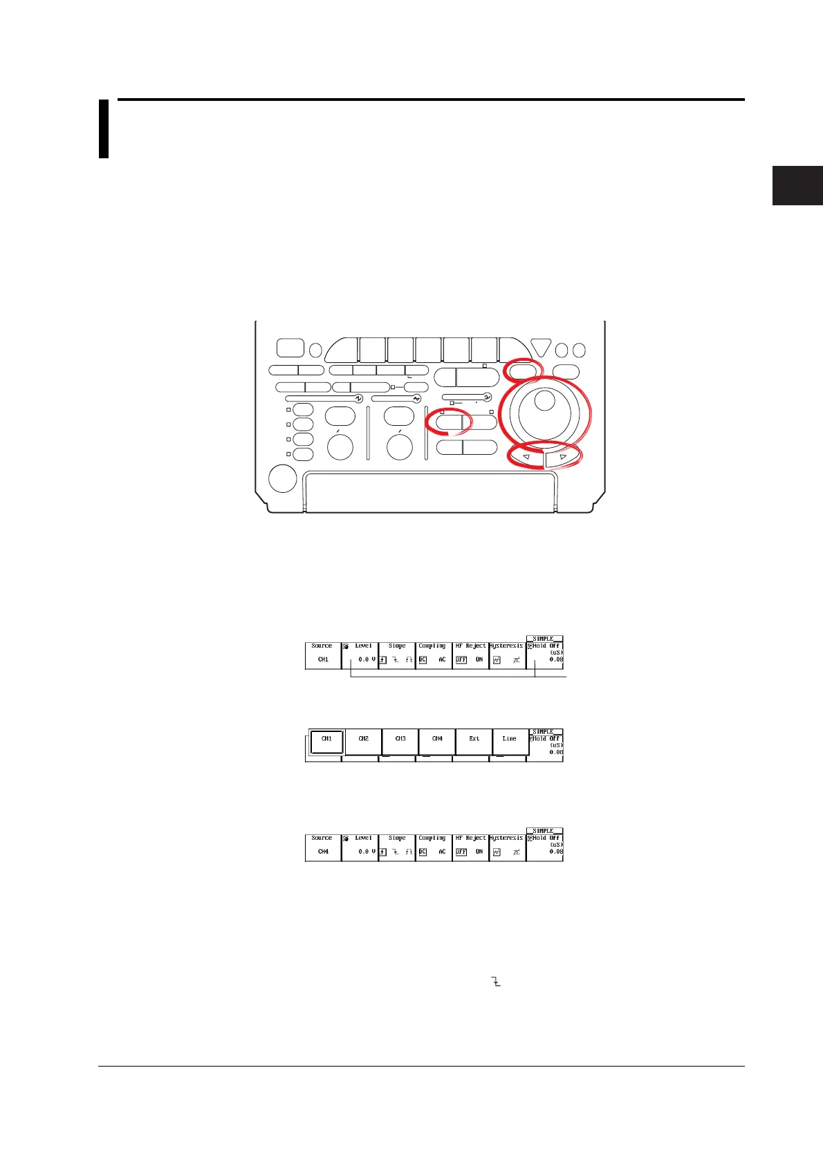
Procedure
1. Press SIMPLE.
Setting the Trigger Source
2. Press the Source soft key to display the trigger source selection menu.
Settings for these items
can be input directly
using a USB keyboard.
3. Press the CH4 soft key.
Setting the Trigger Level
4. Press the Level soft key.
5. Turn the jog shuttle to set the trigger level.
You can move between the digits using the arrow keys. Pressing RESET resets
the trigger level to the current offset voltage.
Setting the Trigger Slope
6. Press the Slope soft key to select
.
Setting the Trigger Coupling
7. Press the Coupling soft key to select DC.

 Loading...


