<1. INTRODUCTION AND GENERAL DESCRIPTION>
1-15
IM 12A01A02-01E 8th Edition : Oct. 01, 2015-00
ATEX and IECEx
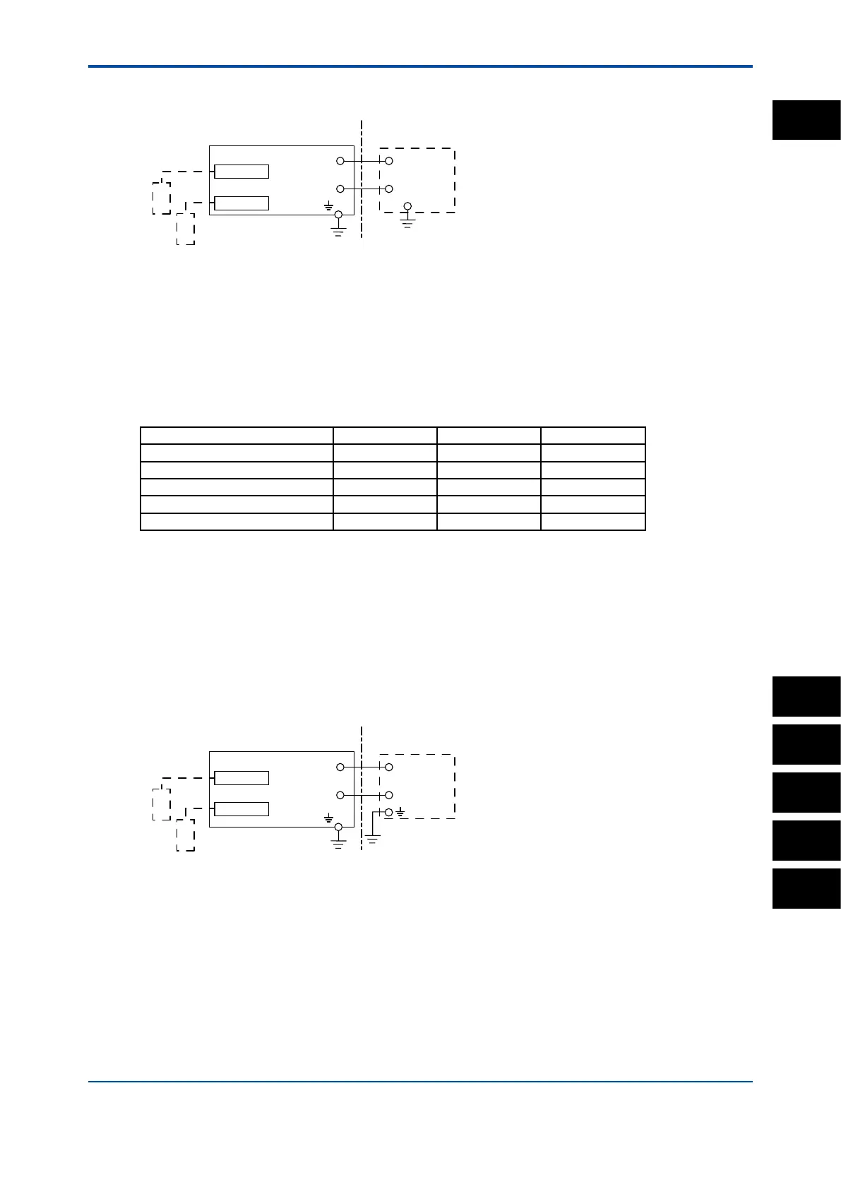
Control Drawing (for 4-20mA type)
Measuring module 1
Note: The measuring module on this drawing means
the sensor module on this General Specifications.
Measuring module
2
Sensor 1
Sensor 2
(*)
(Note 1)
Safety Barrier
Housing Assembly
Supply
-
Supply
+
→
Non Hazardous Location
Hazardous Location ←
-
+
Electrical data are as follows;
Supply and output circuit (Terminals Supply + and -):
Maximum Voltage (Ui) = 30V
Maximum Current (Ii) = 100mA
Maximum Power (Pi) = 0.75W
Internal Capacitance (Ci) = 13nF
Internal Inductance (Li) = 0mH
Sensor input circuit (pH: terminals 11 through 19, SC: terminals 11 through 16, DO: terminals 11
through 18, ISC: terminals 11 through 17, SENCOM: terminals 82, 83, 84, 86 and 87):
Type of Measuring Module pH, SC and DO ISC SENCOM
Maximum Voltage (Uo) 11.76 V 11.76 V 5.36 V
Maximum Current (Io) 116.5 mA 60.6 mA 106.6 mA
Maximum Power (Po) 0.3424 W 0.178 W 0.1423 W
External Capacitance (Co) 100 nF 100 nF 31 µF
External Inductance (Lo) 1.7 mH 8 mH 0.45 mH
Note 1: In any safety barrier used, the output current must be limited by a resistor “R” such that Imaxout=Uz/R.
Note 2: The safety barrier shall be certied by notify body EU as ATEX.
Note 3: When using non isolation barrier connect (*1) to IS earthing system.
Note 4: Sensor 1 and Sensor 2 shall be of passive types to be regarded as ‘simple apparatus’ or the ones individually
certied with relevant parameters.
Note 5: Measuring module 2 may not mounted. As for ISC module and SENCOM module, only one can be mounted.
Note 6: Measuring module is placed in an enclosure with IP20 and over.
FM
Control Drawing (for 4-20mA type)
Following contents refer “DOC. No. IKE039-A12”
Measuring module 1
Measuring module 2
(Refer to Note 7)
Sensor 1
Sensor 2
(Note 1)
Safety Barrier
Housing Assembly
Supply
-
Supply
+
→
Non Hazardous Location
Hazardous Location ←
-
+
Class I, Division 1, Groups A, B, C, and D
Class I, Zone 0 and 1, Group IIC
T4 for Ta = 55°C, T6 for Ta = 40°C
2 wire analyzer
Note: The measuring module on this drawing means
the sensor module on this General Specifications.
Electrical data are as follows;
Input Maximum Input Voltage (Ui) = 30V
Maximum Current (Ii) = 100mA
Maximum Power (Pi) = 0.75W
Internal Capacitance (Ci) = 13nF
Internal Inductance (Li) = 0mH
1
PH
SC
ISC
DO
SENCOM