<1. INTRODUCTION AND GENERAL DESCRIPTION>
1-16
IM 12A01A02-01E 8th Edition : Oct. 01, 2015-00
Sensor Input Circuit
Type of Measuring Module pH, SC and DO ISC
Maximum Voltage (Uo) 11.76 V 11.76 V
Maximum Current (Io) 116.5 mA 60.6 mA
Maximum Power (Po) 0.3424 W 0.178 W
External Capacitance (Ca, Co) 100 nF 100 nF
External Inductance (La, Lo) 1.7 mH 8 mH
Note 1: In any safety barrier used, the output current must be limited by a resistor “R” such that Imaxout=Uz/R.
Note 2: The safety barrier shall be FM Entity-Approved associated apparatus / barrier where :
Barrier Voc, Uo ≤ 30V;
Barrier Isc, Io ≤ 100 mA;
Barrier Po ≤ 0.75W;
Barrier Ca, Co ≥ 13 nF+Ccable;
Barrier La, Lo ≥ Lcable
Note 3: When using non isolation barrier connect (*1) to IS earthing system.
Note 4: pH and SC Sensor(s) are of a passive type to be regarded as ‘simple apparatus’ same as 06ATEX0218X,
06ATEX0219, IECEx KEM 06.0052X, FM3028779, 06ATEX0220X, 06ATEX0221, IECEx KEM 06.0053X or the one
individually certied with relevant parameters.
Note 5: ISC Sensor(s) are ISC40S of 00ATEX1067X or the one individually certied with relevant parameters.
Note 6: DO Sensor(s) are of a passive type to be regarded as ‘simple apparatus’ or the one individually certied with
relevant parameters.
Note 7: Measuring module 2 may not mounted. As for ISC module, only one can be mounted.
Note 8: Install per the National Electrical Code (NFPA 70)
Note 9: WARNING - Potential electrostatic charging hazard Electrostatic charge may cause an explosion hazard. Avoid any
actions that cause the generation of electrostatic charge, e.g., rubbing with a dry cloth.
Note 10:
As an alternative to installing the FLXA21 in Division 2 using Class I, Division 2 wiring methods, the FLXA21 may
be installed in Division 2 using nonincendive eld wiring in accordance with the National Electrical Code (NFPA
70) using the same parameters identied for intrinsically safe entity installations. The Associated Nonincendive
Apparatus shall have nonincendive eld wiring connections which are FM Approved for use in the Class I, Division 2
location.
CSA
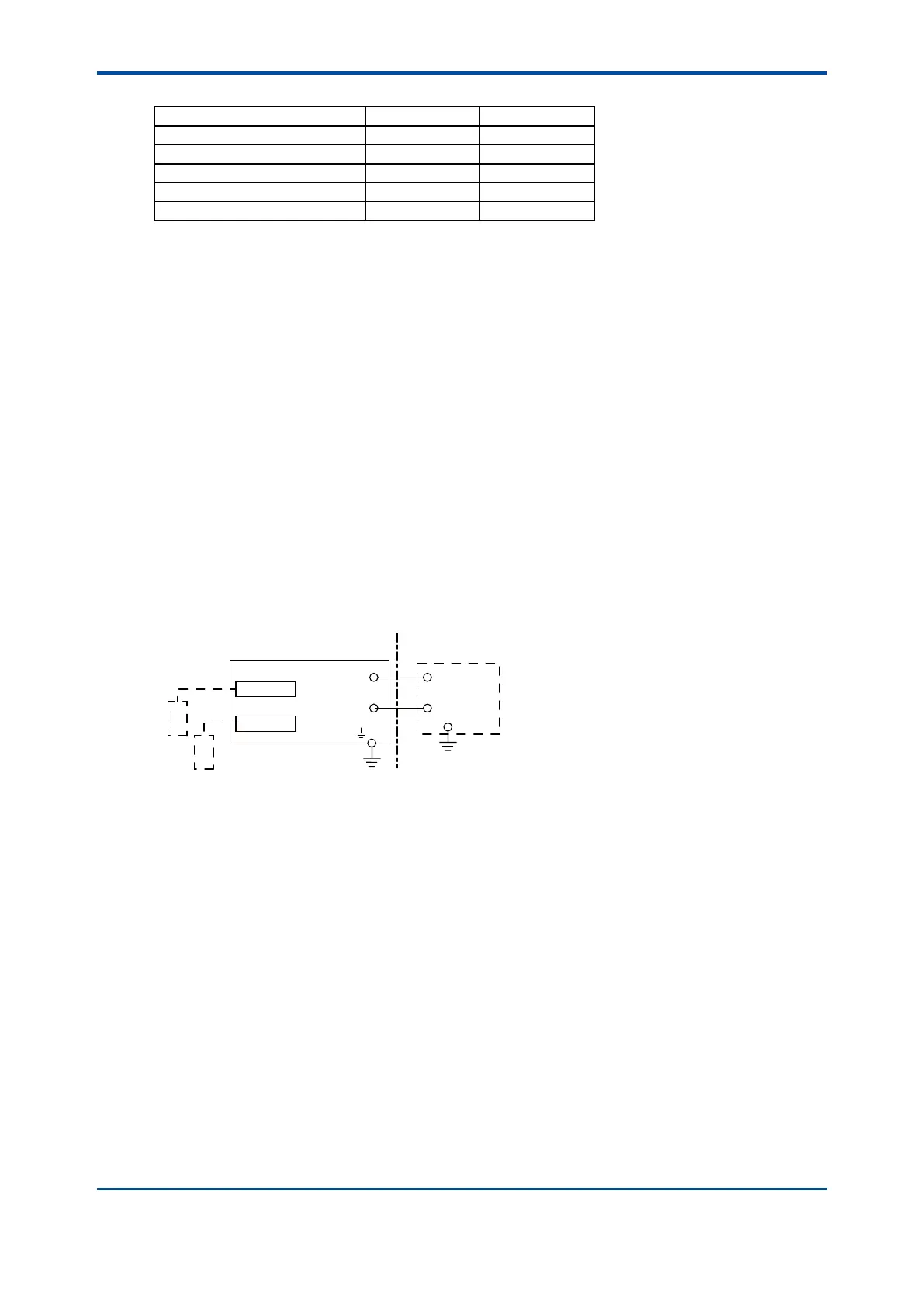
Control Drawing (for 4-20mA type)
Measuring module 1
Measuring module 2
(Refer to Note 7)
Sensor 1
Sensor 2
Housing Assembly
Supply
-
Supply
+
→
Non Hazardous Location
Hazardous Location ←
(*1)
Refer to Note
Safety Barrier
-
+
Intrinsically Safe
Group IIC, Zone 0
Class I, Division 1
Non-incendive
Class I, Division 2,
Groups A, B, C, D
2 wire analyzer
Not use safety barrier but
CSA certified equipment
use in Non-incendive
Note: The measuring module on this
drawing means the sensor module
on this General Specifications.
Electrical parameters (Intrinsically safe)
Housing Assembly
Supply and output circuit (terminals + and -)
Ui(Vmax)=30V, Ii(Imax)=100mA, Pi(Pmax)=0.75W, Ci=13nF, Li=0mH
Measuring module input circuit (CN2 or CN3 on Back board)
Uo(Vt,Voc)=13.65V, Io(It,Isc)=50mA, Po=0.372W, Co(Ca)=80nF, Lo(La)=7.7mH
pH module, SC module and DO module
Ui(Vmax)=13.92V, Ii(Imax)=50mA, Pi(Pmax)=0.374W, Ci=40nF, Li=2.9mH
Sensor input circuit (terminals 11 through 19)
Uo(Vt,Voc)=11.76V, Io(It,Isc)=116.5mA, Po=0.3424W, Co(Ca)=100nF, Lo(La)=1.7mH
ISC module
Ui(Vmax)=13.92V, Ii(Imax)=50mA, Pi(Pmax)=0.374W, Ci=40nF, Li=7.7mH
Sensor input circuit (terminals 11 through 17)
Uo(Vt,Voc)=11.76V, Io(It,Isc)=60.6mA, Po=0.178W, Co(Ca)=100nF, Lo(La)=8mH
Installation requirements between housing assembly and safety barrier
Uo≤Ui Io≤Ii Po≤Pi Co≥Ci+Ccable Lo≥Li+Lcable
Voc≤Vmax Isc≤Imax Ca≥Ci+Ccable La≥Li+Lcable
Uo, Io, Po, Co, Lo, Voc, Isc, Ca and La are parameters of barrier.