<Appendix1.PressureElements>
A1-2
IM 02M04B01-01EN
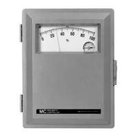
(4) PipingArrangements
FA0103.ai
A
A
AA
C C
C C
Dry Gas Wet Gas
Instrument
above line
Dry
gas
Wet Gas
Line or vessel under
measurement
Instrument
below line
Condensing pipe
(1.2 m of 2" pipe)
Gas-Filled Systems
FA0104.ai
1/2" insulated pipe
Keep as near vertical
as possible.
Liquid Steam
C
C
C
C
B B B
B
A A
A
A
Max height above line =
7.6
specific gravity
(m)
Pipe above
instrument
Gate valve
SteamLiquid
Liquid-FilledSystems
To Zero (Gas application)
Close valve A and open valve C. Use Zero
adjustment to bring the pointer to zero. Close valve
C and open valve A.
Valve C can be used for initial drainage in wet gas
applications with instrument below line.
To Fill Line (before zeroing)
Liquid:
Open valve A. Open valve C until liquid ows
free of bubbles. Close valve C.
Steam:
Open valve A and allow piping between plug B
and instrument to ll with condensate.
ToZero(Liquidandsteamapplication)
After lines are lled with liquid, close valve A and
remove plug B. Use Zero adjustment to bring the
pointer to zero. Replace plug B and open valve A.
A1.2 Calibrationand
Replacement of Pressure
Elements
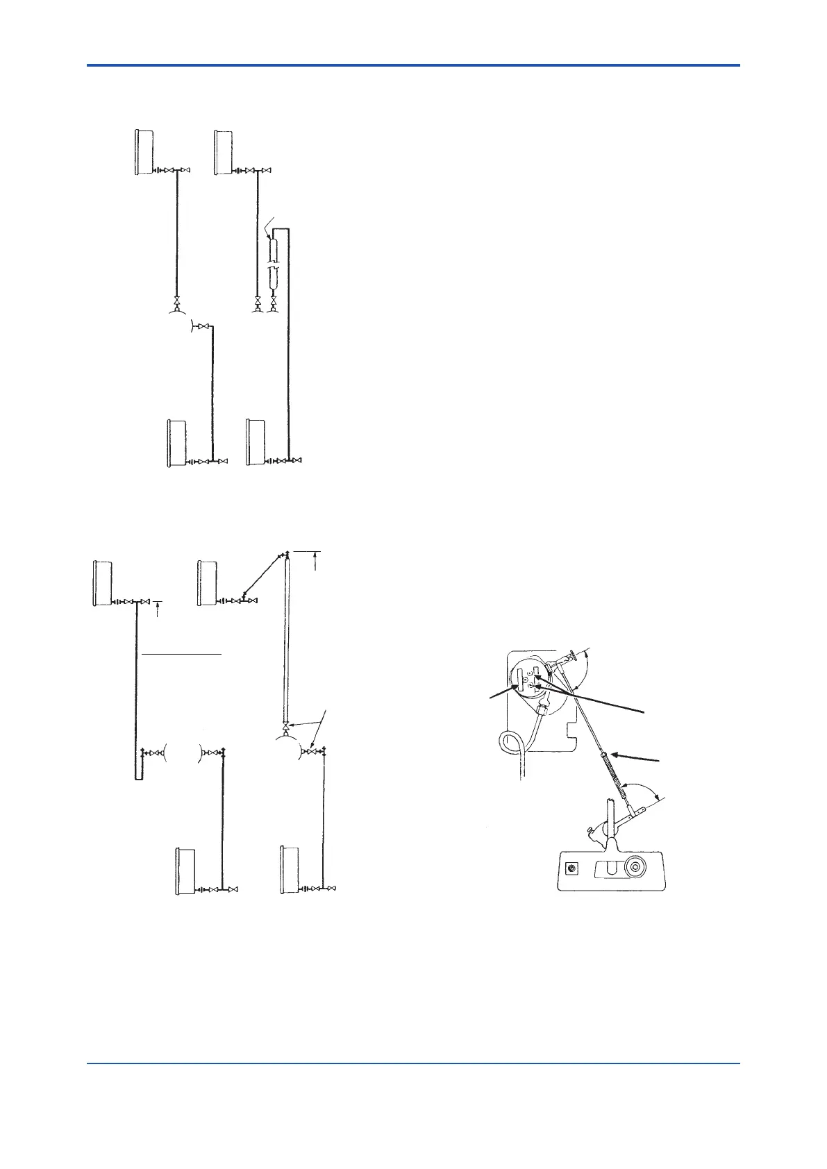
(1) SquaringUpofLinkageforComplete
Calibration
If parts have been replaced, or for some other
reason a complete recalibration is necessary,
square up the linkage before the actual calibration.
FA0105.ai
3
b
a
2
1
1. Set pressure at middle of element range (see
range on element nameplate).
2. Obtain right angle (a) by loosening the two
screws on top of element and slipping drive
lever on its shaft.
3. Obtain right angle (b) by adjusting length of link.
 Loading...


