<2. General>
2-2
IM 02M04B01-01EN
2.3 Principle of Operation
F0201.ai
1
2
3
4
5
6
Measurement
Local or remote
Proportioning
lever
Error
signal
Proportioning
bellows
Flat spring
Reset
bellows
Flapper
nozzle
Flapper
Striker bar
Reset restrictor
Derivative
restrictor
Reducing
tube
Amplifier
Shutoff
valve
Regulator Balance
indicator
Auto/Man
switch
Auto Man
Air supply
140 kPa (1.4kgf/cm
2
)
Output
Set point
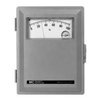
Figure 2.1 Controller with Proportional, Reset,
andDerivativeActions,andAutomatic,
Manual Transfer System.
1. A differential linkage measures difference
between measurement pointer and setting
index positions. This error signal moves
proportioning lever.
2. Proportioning lever pivots at its center on end of
a at spring.
3. This motion changes apper nozzle
relationship, causing amplier to establish an
output pressure.
4. Output pressure is fed back to proportioning
bellows, which acts through proportioning lever
to rebalance apper-nozzle.
5. Reset bellows and tank assembly are used
when measuement must be maintained exactly
at control point (without “offset”).
6. Derivative tank assembly is used to improve
system response to a slow process.
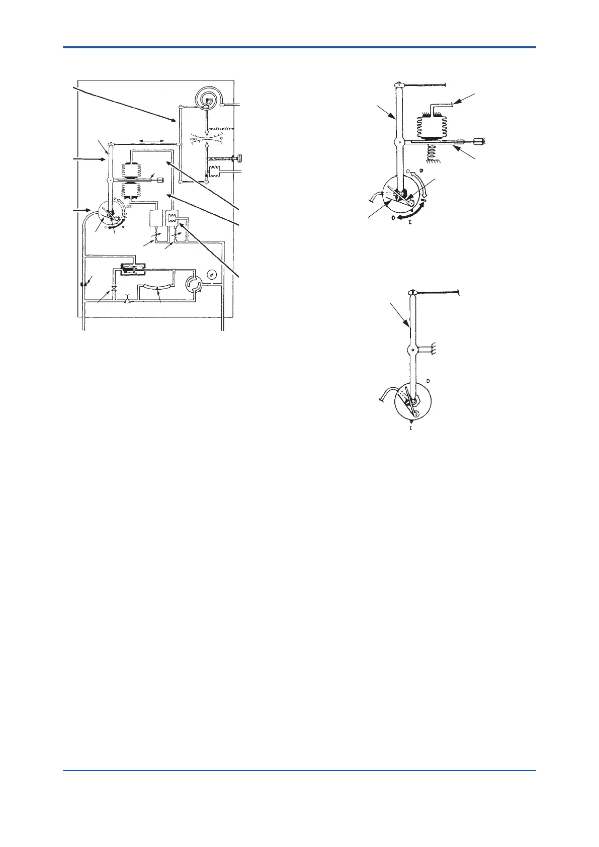
(1) Proportional Control
F0202.ai
Proportioning lever
Feedback from
relay output
Proportioning bellows
Flat spring
Striker bar
Flapper
For description, see Steps 1 through 4.
(2) On-Off Control
F0203.ai
Proportioning lever
Flapper nozzle
On-Off control is obtained by pivoting the
proportional lever about a xed point without
proportioning or reset bellows. This controller can
be equipped with an automatic shutdown unit.
 Loading...


