5
CMPL 02M04B01-01E
Nov. 2015
Subject to change without notice.
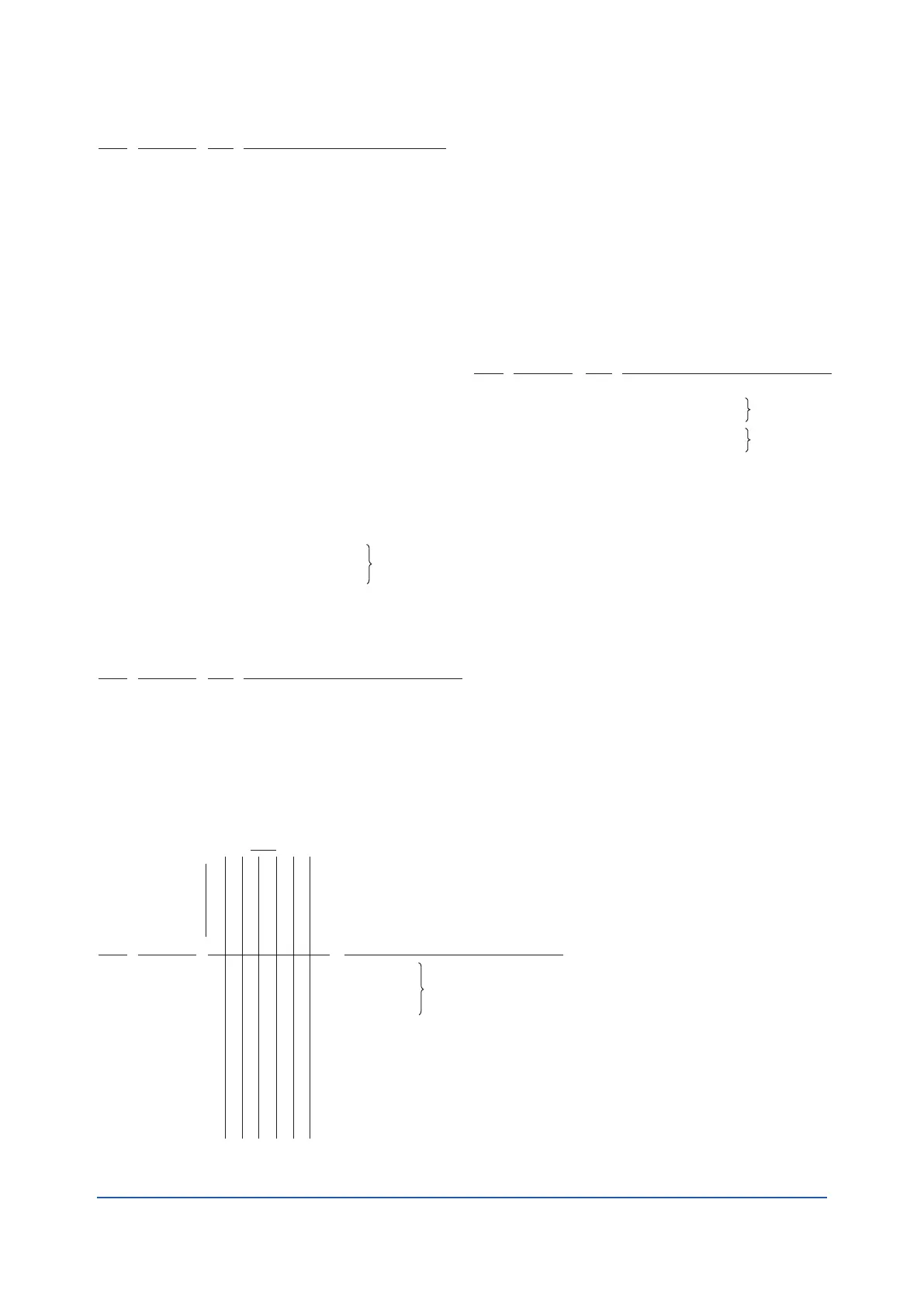
Measurement Pointer
Setting Index
Tubing
Output Gauge Assembly
for Option Code/CAL-M
for Option Code/CAL-E
for Standard and Option Code/CAL-Q,
0 to 200 kPa
for Option Code/CAL-B, 0 to 2 bar
A/M Switch and Manual Regulator
Control Mode: A1, A3, A5 and A7*
1
Control Mode: A2, A4 and B4*
1
Pan H. Screw, M4 x 25
Manifold Assembly
JIS Connection
ANSI Connection
*Screen
Pan H. Screw, M5 x 10
Gasket
Tubing
Tubing (give length)
For A3, A4, A5 and B4
Pressure Element
and Mounting Parts
Link Assembly
1
2
6
7
8
9
10
11
12
13
14
15
16
17
M0154WL
M0154WN
R0128AA
Below
F9123GJ
F9123GK
F9123GL
F9123GM
Below
C0140QM
F9120NM
Y9425JS
Below
F9123QA
F9123QF
U0103FP
Y9510JU
C0140QQ
F9123QX
R0128AA
–
–
1
1
1
1
1
3
1
2
2
1
2
–
1
1
Item Part No. Description
Qty
Receiver Element Assembly
Lever Assembly
Link Assembly
Column
Pan H. Screw, M4 x 8
Compression Screw
Sleeve
Tube
18
19
20
21
22
23
24
25
U0101CP
F9120YG
X0101CS
F9123JK
Y9408JS
U0100CB
X0107AA
U0110BM
1
1
1
2
2
2
2
1
Item Part No. Description
Qty
Control Unit
Control Unit
Control Unit
Control Unit
Restrictor Unit (Integral) Prior to Oct. 1, 1989: Contact Yokogawa
Restrictor Unit (Derivative) Prior to Oct. 1, 1989: Contact Yokogawa
Pan H. Screw, M4 x 8
Cap Assembly
(with auto/manual transfer switching)
Tee
Pan H. Screw, M4 x 12
26
27
28
29
30
31
32
C0140ZV
C0140ZU
C0140ZS
C0140ZT
F9138QS
F9138RD
Y9408JS
C0138BM
F9136ME
Y9412JS
1
2
2
1
1
2
1
1
2
1
2
1
1
2
2
1
1
1
4
1
1
2
1
2
2
1
1
2
2
Item Part No. Description
Control Mode*1
A1
A2
A3
A4
A5
A7
B4
Qty
Description
–
33
34
35
36
37
–
–
38
39
40
41
42
43
44
45
Below
F9123RH
F9123RJ
F9123RF
F9123RG
F9138YA
C0100EM
U0113AK
U0110AX
C0140GT
C0127CN
C0127CM
0052645
U0103FP
F9120HN
Below
F9123RM
F9123RN
F9123RK
F9123RL
U0113AY
Y9500SP
Below
C0128MF
C0128KE
C0128LW
C0127CN
1
1
1
1
1
1
1
1
1
2
1
1
2
2
1
–
Item Part No.
Qty
Manifold Assembly
JIS Connection
ANSI Connection
JIS Connection
ANSI Connection
*Pneumatic Amplifier, 80A
*Gasket
Plate
Gasket
Orifice Screw Assembly
*O-Ring, 3/16ID x 5/16OD
*O-Ring, 1/18ID x 1/4OD
6-32 x 7/32 B.H. Screw
*Screen
Clamp
Relay Manifold
For F9123RH
For F9123RJ
For F9123RF
For F9123RG
10-32 x 1-1/18 Hex. H. Screw
Lockwasher
Connection Assembly
One Connection (for control mode;
-A1N and -A7N)
Two Connection (for control mode;
-A2N, -A3N and -A5N)
Three Connection (for control mode;
-A4N and -B4N)
O-Ring
Refer to CMPL
06P01B01-02E
Remote Pneumatic
Set Point Code : -N
For Set Point Code "-P", contact Yokogawa
Control Mode:
A1, A3, A5 and A7*
1
Control Mode:
A2, A4 and B4*
1
NOTE: *
Denotes parts more frequently replaced.
*1 Contol Mode;
A1.....On-off
A2.....Proportional
A3.....Proportional + Derivative
A4.....Proportional + Integral
A5.....Proportional + Integral + Derivative
A7.....Differential Gap
B4.....Batch + Proportional + Integral
Manifold Assembly without A/M Switch
Remote Set Associated Parts
(Applicable model: MC43-N-*A)
 Loading...


