Stamp Company : Stamp Certification Institute :
Signature : Remarks :
Model EXA PH202S-B & PH202S-D
No revision to drawing without prior
FM Approval
Title : FM Control Drawing PH202S-B & PH202S-D (Non-incendive Entity
concept)
Number : FF1-PH202S-00 Page : 10 of 10
Revision : 5.4
YOKOGAWA EUROPE B.V.
Date : 01/07/2004
〈 Sensor(s) are of a passive type to be regarded as ’simple apparatus’, devices which neither store nor
generate voltages over 1. 5 V, currents over 0.1 A, power over 25 mW or energy over 20
µJ, or are FM
Approvals entity approved and meet connection requirements.
〈 Electrical data of the EXA PH202S-B & PH202S-D:
- Supply circuit: Vmax=32 V; Pi=1.2 W; Ci= 737 pF; Li= 2.6 H
- Sensor input circuit: Vt=14.4 V; It=32.3 mA; Ca=600 nF; La=36 mH
When installing this equipment, foll ow the manufacturers installation drawing.
Installation shall be in accordance with Article 501.4(B) of the National Electrical Code (ANSI/NFPA 79).
Nonincendive field wiring may be installed in accordance with Article 501.4(B)(3)
〈 Grounding shall be in accordance with Article 250 of the National Electrical code.
WARNING
- Substitution of components may impair suitability for Division 2.
- Do not remove or replace while circuit is live unless area is know to be non -hazardous
- Explosion Hazard — Do not disconnect equipment unless area is know to be non -hazardous
- Do not reset circuit breaker unless power has been removed from the equipment or the area is know to be non -
hazardous
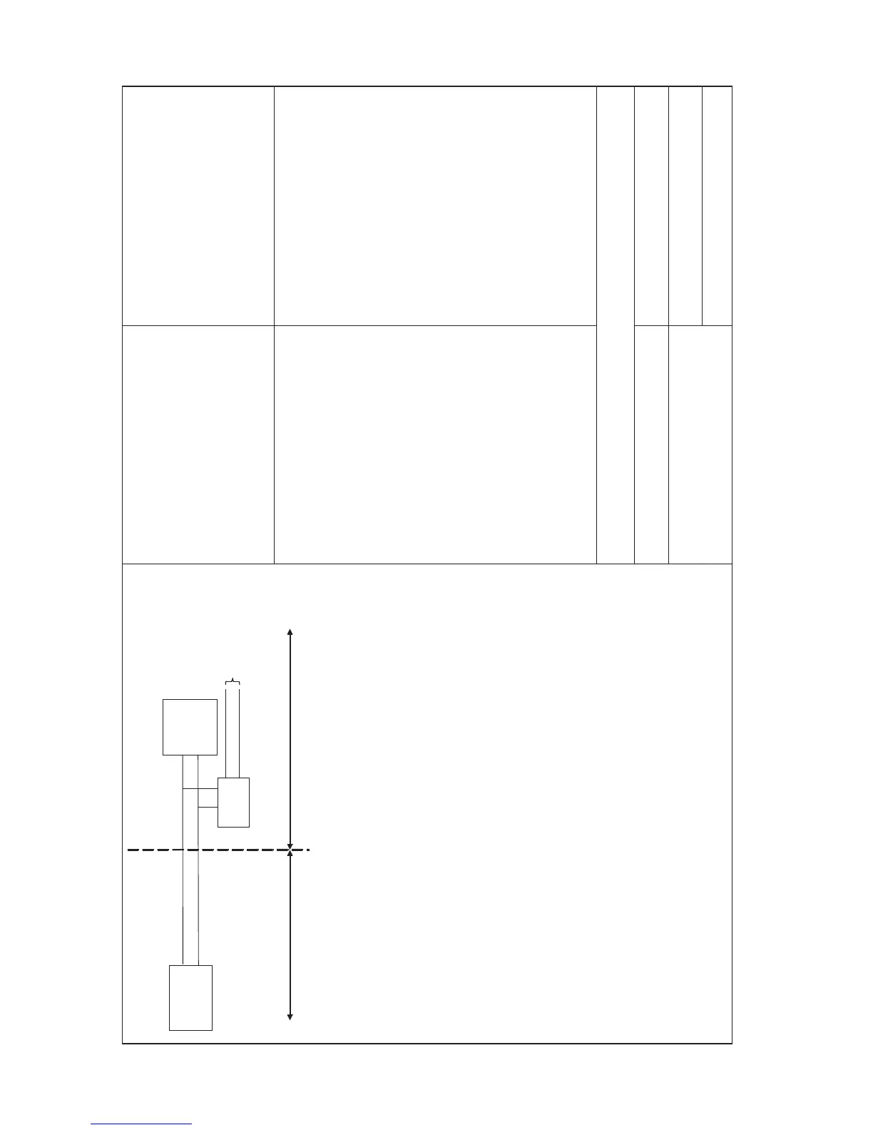
Unclassified Location
Classified Location
Division 2
FM Approved
Power Supply
Voc
¡Ü 32 VDC
FM Approved
Terminator
R = 90..100
C = 0..2,2 F
EXA
PH202S-B
& PH202S-D
Sensor
Connections
Max. cablelength: 60 mtr.
Cable dia.: 3 12 mm.
FM Class I, DIV. 2, Group ABCD
T3B for ambient temp.
≤ 55 ϒC
T4 for ambient tem

 Loading...


