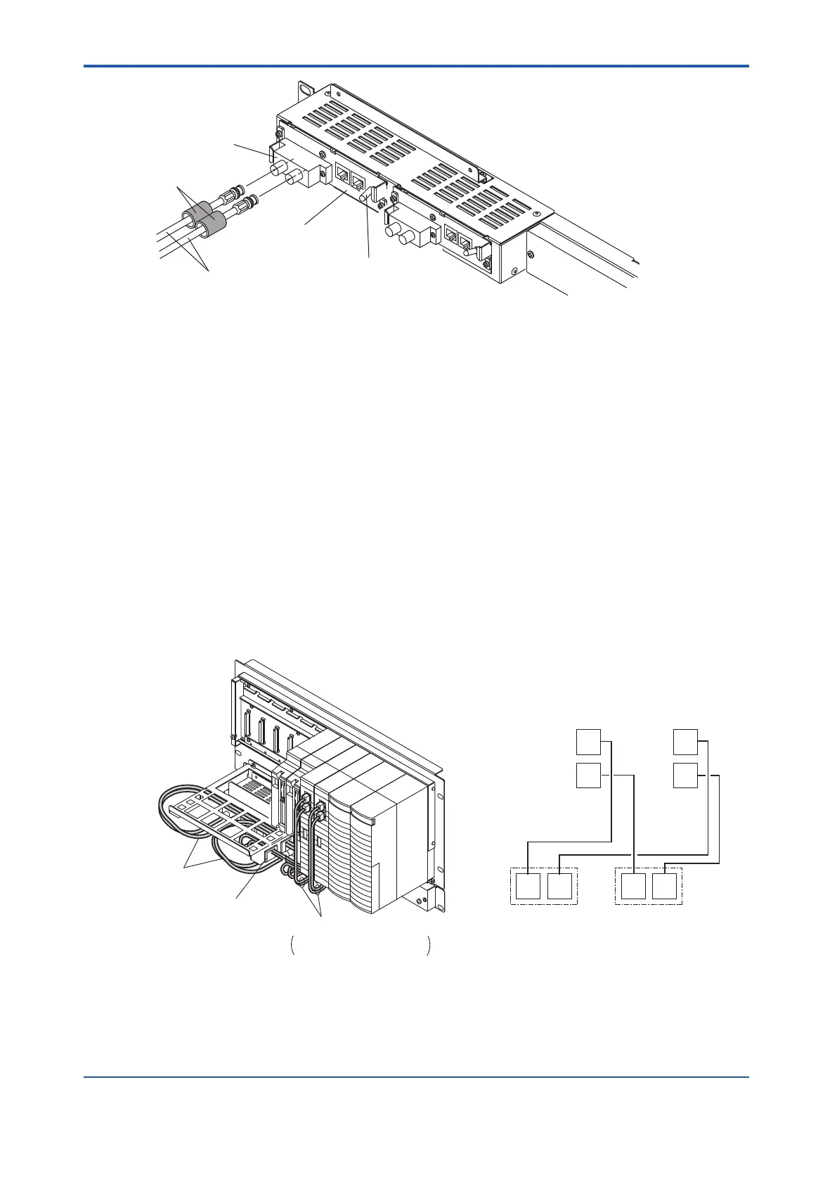
V net cable
V net coupler unit
V net branch
connector
Communication switch
Cover
Figure 3.3.1-2 Connecting V net Cable
n
Wiring of V net Coupler Cable
A V net coupler cable is used to link the V net coupler unit and processor module. The modu-
lar connectors with keys are used on each side of the cable. Connect the connectors as illus-
trated in the following figure. However, following drawing shows a dual-redundant system. If
the processor is single, CN3 will not be used.
• Use the bus1 cable to connect CN2 of coupler unit to BUS1 connector on left side pro-
cessor module.
• Use the bus1 cable to connect CN3 of coupler unit to BUS1 connector on right side pro-
cessor module.
• Use the bus2 cable to connect CN2 of coupler unit to BUS2 connector on left side pro-
cessor module.
• Use the bus2 cable to connect CN3 of coupler unit to BUS2 connector on right side pro-
cessor module.
The wiring route is shown in the following figure. The cable can be pulled through the corner
hole of the cable tray.
Bus 1 (left side)
coupler unit
CN2
CN3
Bus 2 (right side)
coupler unit
CN2 CN3
BUS1
BUS2
BUS1
BUS2
Left side
processor module
Right side
processor module
Cable between V net coupler
unit and processor module
Corner hole
of cable tray
V net coupler cable
V net cable
Figure 3.3.1-3 V net Coupler Cable Route
<3.3 Connecting Control Bus Cables > 3-11
IM 32Q06C10-31E 4th Edition : Jan.30,2015-00
 Loading...
