SEE
ALSO
For more information about connecting and disconnecting the V net coupler cable, refer to:
• 7.2.1, “Replacing V net Coupler Unit” on page 7-7
• 7.2.3, “Replacing Processor Module” on page 7-10
n
V net Conversion
Connecting the devices with dif
ferent size of V net cables is explained as follows.
l
Using the Control Bus Conversion Adapter
Control bus conversion adapter (Model : YCB147) is an adapter for connecting the V net ca-
ble (10BASE-5) with V net cable (10BASE-2).
An BNC type connector is provided on one side of YCB147. The V net cable (10BASE-2)
from safety control unit is connected on this connector.
The other side of YCB147 is provided with N type connector,
the V net cable (10BASE-5) is connected on this connector.
It is required to install the clamp filters to V net cables.
V net cable
(10BASE-5)
V net cable
(10BASE-2)
BNC-type connector
N-type connector
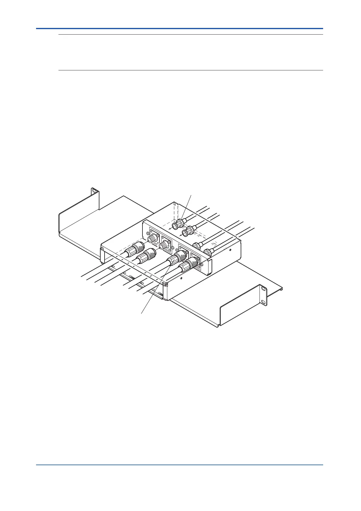
Figure 3.3.1-4 Adapter for Connecting the V net Cable (10BASE-2) with V net Cable (10BASE-5)
l
Using the Control Bus Converter Unit
V net cable (10BASE-2) and V net cable (10BASE-5) can be connected via the control bus
converter unit (YCB149).
However
, the weight and strength of the cables are different, the control bus converter unit
needs to be fixed firmly as follows.
• Fix the control bus converter unit as close as possible to the V net connector to reduce
the load of the bus.
• Fix the control bus converter unit somewhere near safety control unit above the floor level
to make maintenance convenient.
• Place the control bus converter unit in an area isolated from human traffic.
• On the 10BASE-5 V net cables, clamp filters are attached.
The following figure shows an example of the control bus converter unit installation.
<3.3 Connecting Control Bus Cables > 3-12
IM 32Q06C10-31E 4th Edition : Jan.30,2015-00
 Loading...
