4-8
<Toc> <4. Troubleshooting and Maintenance>
IM 05D01D02-41E
3.
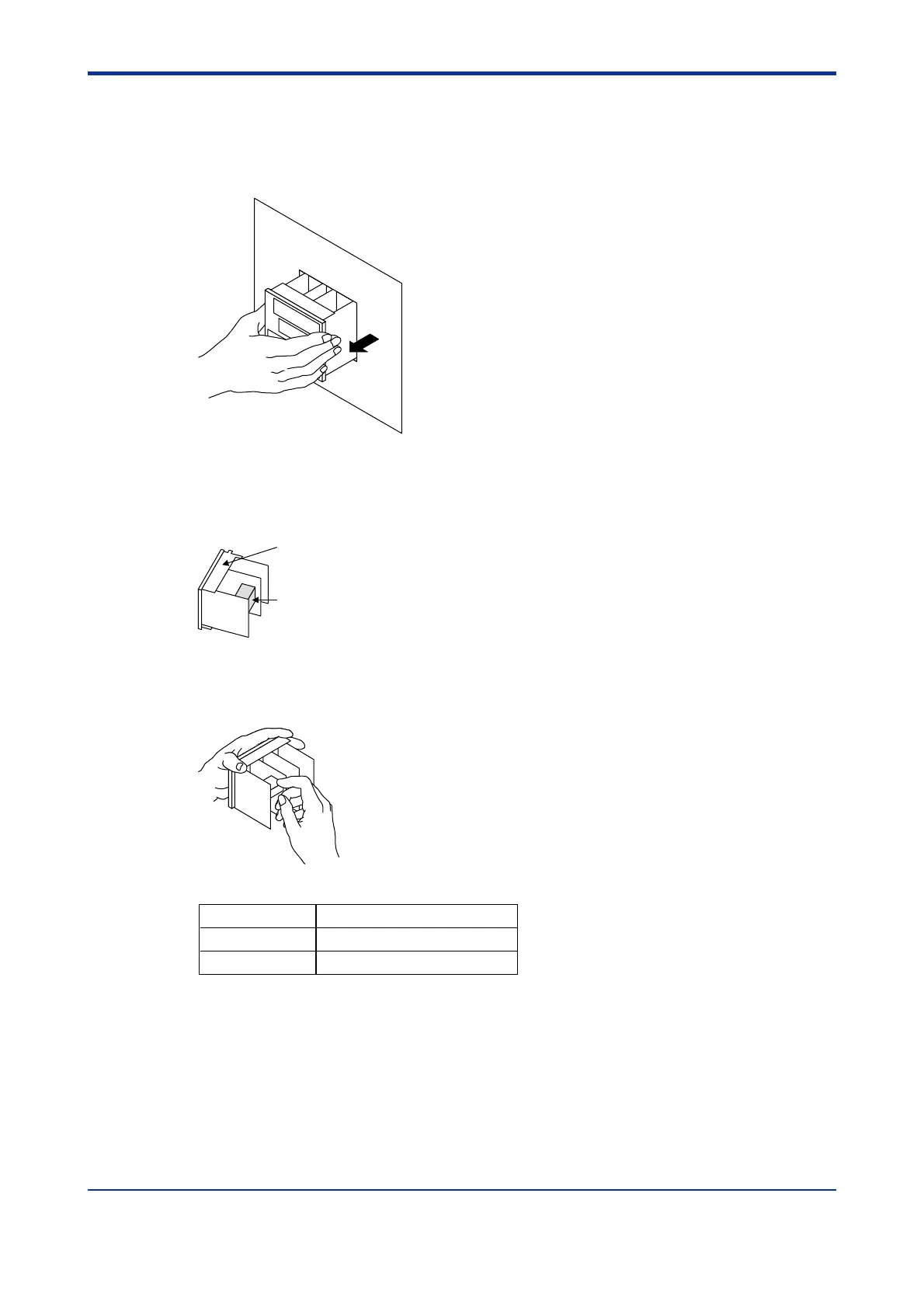
Insert the screwdriver into the four openings and flip the tip forward to move the bezel
more forward.
4.
Hold the bezel and pull it along with the internal unit out of the housing.
(Note) Be careful not to damage the RJC sensor.
5.
The location and number of the relays differ depending on the model code of the UT350/
UT320.
Confirm the location of the control output relay to be replaced before pulling out the
relay.
Relay (UT350-0䊐 or UT320-0䊐)
Upper
6.
Pull out the relay to be replaced.
The control output relays are easy to remove and mount, since they are connected via a
socket onto the print boards.
Insert the new relay in the socket. Use the following relay.
Manufacturer OMRON
Model G6B-2114P-FD-US-P6B
Power supply 12 V DC
1st Edition : May 31,2000-00

 Loading...