<Toc> <6. Function Block Diagram and Descriptions>
6-3
IM 05D01D02-41E 1st Edition : May 31,2000-00
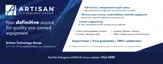
■ Function Block Diagram for Heating/Cooling Type
DI1 DI2
Contact input
SP.NO
Target setpoints 1 to 4
SP.NO=0
LOCALREMOTE
Control computationManual operation
AUTO (ON)/MAN (OFF) switching
AUTOMAN
A/M
*1 *1
DO3
DO2DO1
Alarm 1 Alarm 2
Relay
PV input
terminals
, and
12 1311
PV INPUT
Input selection
Unit selection
Input range conversion
Input bias
Input filter
Communication
terminals to
RS485
2723
Heating/cooling
computation
Heating-side
preset output
Heating-side
output limiter
Cooling-side
preset output
Cooling-side
output limiter
OT
Heating-side
output
OUTPUT1 OUTPUT1
1716
Current or pulse
terminals
and
Relay
terminals
, and
2 31
OT
OUTPUT2
/RET
Current or pulse
terminals
and
1514
Cooling-side
output
RET
15 V loop
power supply
Retransmission
output
Current
terminals
and
1514
Alarm function
SP.NO=1 to 4
Target setpoint
ramp-rate function
OUTPUT2
/LPS
*1: If the setup parameter DIS (DI function selection) is set to “4”,
when the contact input 2 is ON (stop state), that controller outputs the preset output value.
Terminal Parameter Function
Analog signal Contact signal Front panel key
Legend

 Loading...