6-4
<Toc> <6. Function Block Diagram and Descriptions>
IM 05D01D02-41E 1st Edition : May 31,2000-00
Functions and Parameters for “Standard Type” in Initial State (Factory-set
default)
Functions and parameters in initial state are given in the tables below. For details on each
parameter, refer to “5.2 Lists of Parameters.”
■ PV Input
PV input (INPUT) is a universal input, which can receive signals from thermocouple, RTD,
or DC voltage signals. The controller is capable of biasing, and first-order lag computation
(filtering) on input signals.
Each function can be set by the following parameters.
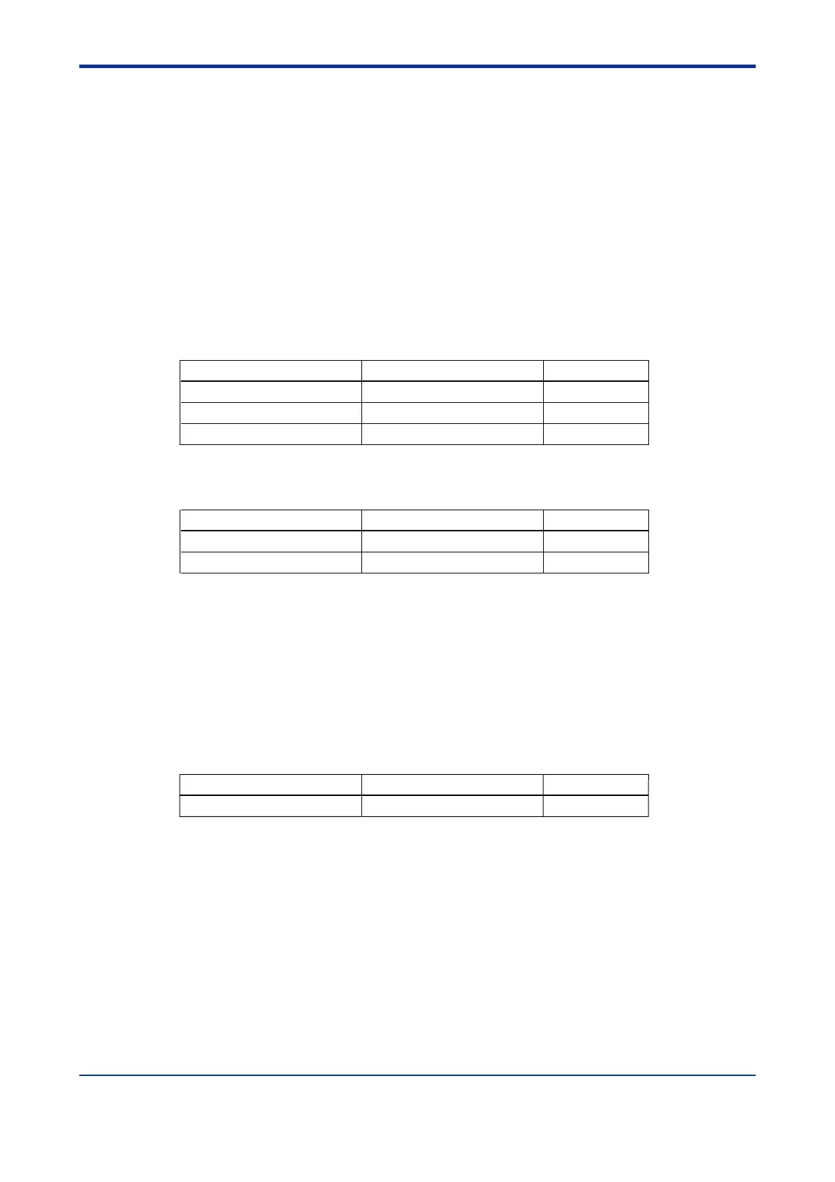
Setup Parameters
Function Parameter
Input selection IN
Unit selection UNIT
Input range conversion RH, RL (SDP, SH, SL)
I/O
I/O
I/O
Menu
Operating Parameters
Function Parameter Menu
PV input bias BS OP.PA
PV input filter FL OP.PA
■ Remote Input
Remote input can be received via communication. Set “0” in the parameter SP.NO (target
setpoint number selection) for remote input. For more information, refer to GREEN Series
Communication Functions (IM 05G01B02-01E).
Each function can be set by the following parameters.
Operating Parameters
Function Parameter
Target setpoint number selection
SP.NO OP.PA
Menu

 Loading...