<Toc> <6. Function Block Diagram and Descriptions>
6-7
IM 05D01B02-41E 1st Edition : May 31,2000-00
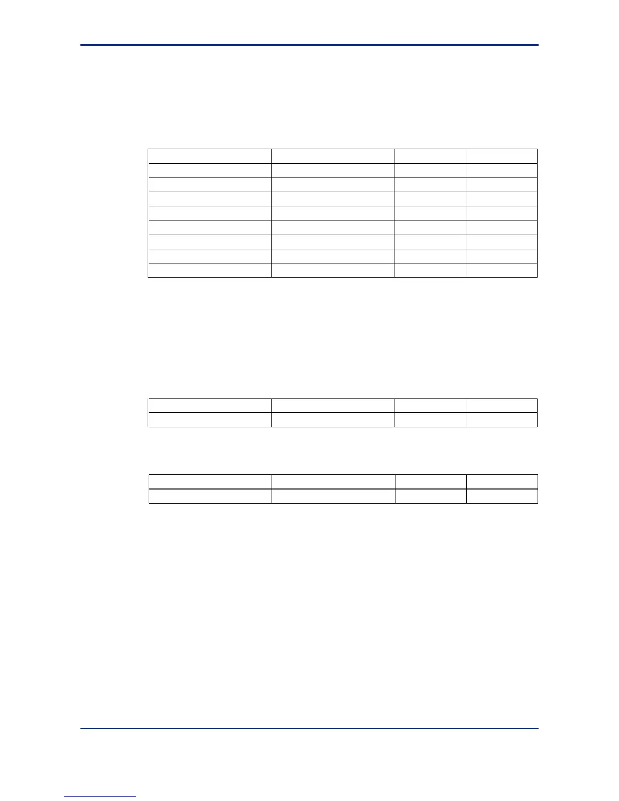
■ Target Setpoint and PID
It is possible to use a maximum of eight groups of target setpoints and PID parameters.
The target setpoint can be selected by key operation or contact input. For selection by
contact input, refer to “Contact Input.”
Operating Parameters
Function Parameter
Target setpoint number selection
SPNO
Target setpoints 1 to 8 n.SP
Proportional band (P) n.P
MODE
LP1
LP1
None
n.PID
n.PID
Integral time (I) n.I
Derivative time (D) n.D
LP1
LP1
n.PID
n.PID
n.Pc LP1 n.PID
n.Ic
n.Dc
LP1
LP1
n.PID
n.PID
Cooling-side proportional band (Pc)
Cooling-side integral time (Ic)
Cooling-side derivative time (Dc)
Main menu Submenu
Note: Parameters n.SP, n.P, n.I, n.D, n.Pc, n.Ic, n.Dc (n=1 to 8) correspond to the target setpoint number selected in the
target setpoint number selection (SPNO).
The target setpoint ramp rate setting function prevents the target setpoint form changing
suddenly. It is possible to set the upward and downward changing rate (i.e., ramp rate)
independently in the parameters UPR and DNR. The unit of the ramp rate (hour, or minute)
is specified in TMU.
Setup Parameters
Function Parameter
Ramp-rate time unit setting TMU LOOP1 SP
Main menu Submenu
Operating Parameters
Function Parameter
Target setpoint ramp-rate setting
UPR, DNR LP1 PAR
Main menu Submenu

 Loading...


