6-9
IM WT5000-01EN
Trigger Level (Trigger Level)
The trigger level is the level at which the trigger slope is determined. When the trigger source passes through
the trigger level on a rising or falling edge, a trigger occurs.
• You can select a value between 0.0 and ±100.0%.
• A value of 100% corresponds to half the height of the waveform display. If the zero level of the input signal
is set to the center of the vertical axis, 100% corresponds to the top of the waveform display, and –100%
corresponds to the bottom of the waveform display. The upper and lower limits of the waveform display
correspond to three times the voltage or current measurement range of each element when the crest factor is
set to CF3. Likewise, the limits are six times when the crest factor is set to CF6 or CF6A.
• When Ext Clk is set as the trigger source, the trigger level setting is invalid.
Trigger level
This instrument triggers here (the trigger point)
when the trigger edge is set to rising ( ).
Trigger source
Input zero line
(center of the
vertical axis)
100% (300 Vpk)
−
100% (
−
300 Vpk)
• Measurement range: 100 Vrms when the crest factor is set to CF3.
50 Vrms when the crest factor is set to CF6 or CF6A.
• Trigger level: 25%
25% trigger level (75 V)
T
Trigger level
If you do not set the trigger level properly, the waveform display start point (the signal level on the left edge of
the screen) may be unstable, or waveforms may not appear.
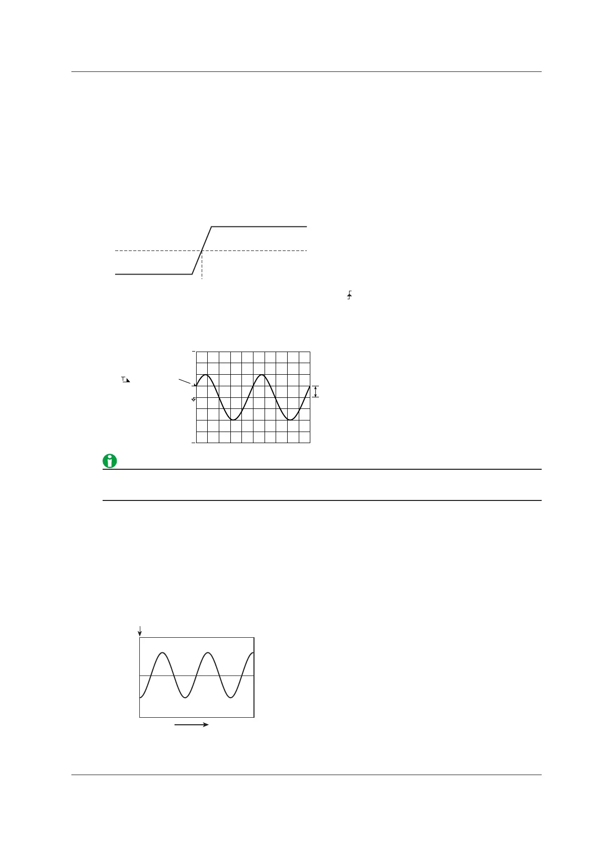
Trigger Point
The trigger point is the point at which a trigger occurs. The trigger point is always displayed at the left end of the
screen.
After the trigger is activated, the waveform display continues from the left of the screen to the right of the screen
with the passage of time.
(The arrow below the word “Trigger point” in the figure below is just for illustration. The arrow does not appear on
the actual display.)
6 Computation and Output
 Loading...


